Hub and Spoke Layer 2 VPNs between multiple NSX-T enabled sites
In this wiki article, I will explain how to set up Hub and Spoke Layer 2 VPNs between multiple NSX-T enabled sites.
Acknowledgement
This article was written by me (Iwan Hoogendoorn) and I worked together with Bal Birdy to make L2 VPN across multiple sites work from a technical perspective.
Software Versions used in this article
| Software | Version |
|---|---|
| vCenter Server | 7.0.1 (17005016) |
| ESXi | 7.0.1 (16850804) |
| NSX-T | 3.1 |
Configuration Steps
The configuration steps are different for the Hub and Spoke sites.
One of the pre-requisites is that you already have the following in place (on each site):
- Physical routers (that interconnect the three sites)
- A Tier-0 Gateway (attached to the physical "DCI" routers)
- A Tier-1 Gateway attached to the Tier-0 Gateway
- A Segment (with the same subnet) attached to the Tier- Gateway
- Test Virtual Machines attached to the segment
L2-VPN Server side - HUB
- STEP 1) Create VPN Services for IPSEC
- STEP 2) Create VPN Services for L2 VPN SERVER
- STEP 3) Create a Local End Point
- STEP 4) Create L2 VPN Sessions (one for each spoke location)
- STEP 5) Link the local L2 Segment to the L2 VPN session
- STEP 6) Advertise VPN Endpoint addresses
L2 VPN Client-side - Spoke
- STEP 1) Create VPN Services for IPSEC
- STEP 2) Create VPN Services for L2 VPN SERVER
- STEP 3) Create L2 VPN Sessions (one for each spoke location)
- STEP 4) Link the local L2 Segment to the L2 VPN session
- STEP 5) Advertise VPN Endpoint addresses
Multi-site Layer-2 VPN Network Topology
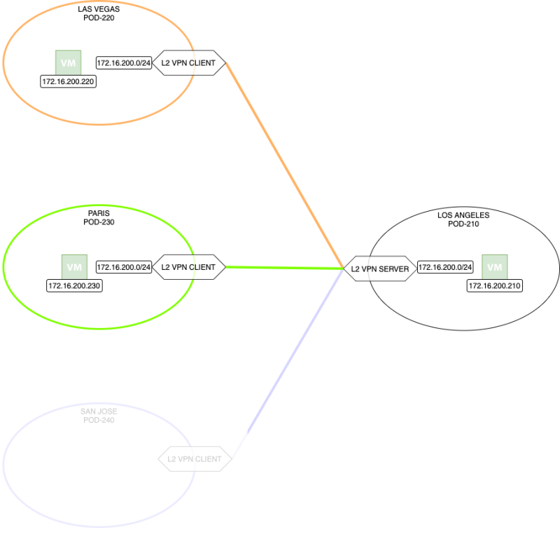
In this article, I am going us the following diagram to build the Layer 2 VPN Hub and Spoke topology. The goal is that the subnet 172.16.200.0/24 that is now local to each site will now be stretched with the help of using the Layer 2 VPN features used by NSX-T. NSX-T is running within each site. Each site will be referred after this with a Pod.
- Pod-210 (Hub / Server )
- Pod-220 (Spoke / Client )
- Pod-230 (Spoke / Client )
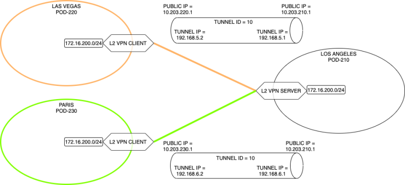
This drawing shows the different IP addresses used:
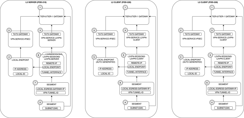
NSX-T Object Interaction and Dependancy
To configure a lot of objects need to be created and some of these objects have dependencies on others. The figure below will show the dependencies and the order of creation to make this a bit easier to understand.
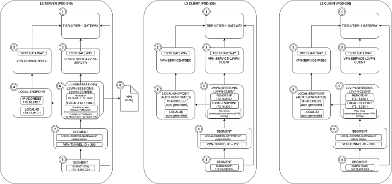
To make the deployment easier I have also specified some of the details (like IP addresses) to make sure the implementation is easier.
Pay attention to the VPN configuration that is generated on the server-side that contains a "peer code" that needs to be entered at the client-side to retrieve some configuration details that are enforced by the Server.
L2-VPN Server side HUB Configuration Steps
Pod-210
I am starting with the server-side configuration.
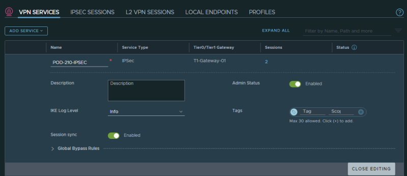
STEP 1〉 Create VPN Services for IPSEC
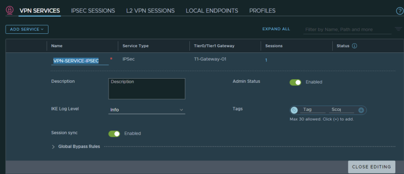
Create a VPN Service for IPSEC:
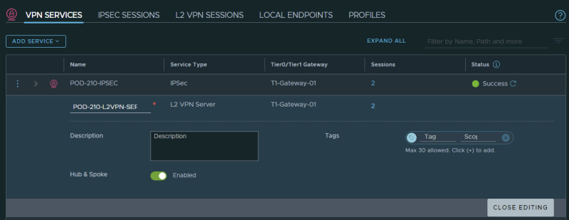
STEP 2〉 Create VPN Services for L2 VPN SERVER
Create a VPN Service for L2 VPN SERVER:
You can also create a VPN Service for a Layer 2 CLIENT, this will be done on the client-side, and here we create the L2 VPN SERVER VPN Service.
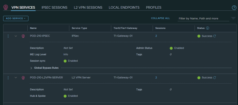
When both VPN Services are added this is the summary of how it should look like:
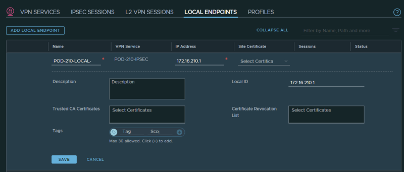
STEP 3〉 Create a Local End Point
Create a Local End Point:
STEP 4〉 Create L2 VPN Sessions 〈one for each spoke location〉
Now it is time to create a Layer 2 VPN Sessions towards the spokes.
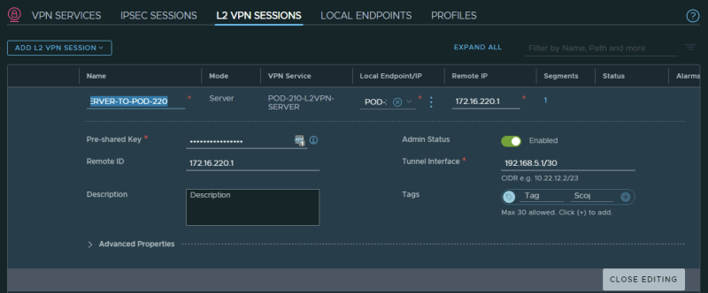
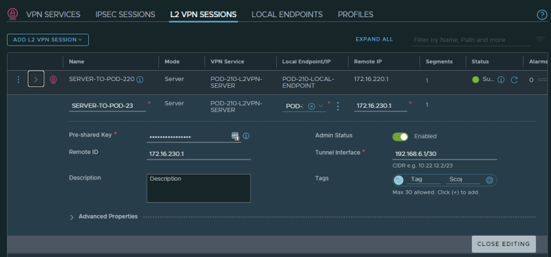
Below you will have the option to configure the details for a "tunnel interface" this IP address range is DIFFERENT from the actual Local/Remote (peer) IP addresses!
Create a Layer 2 VPN Session towards Pod-220:
Create a Layer 2 VPN Session towards Pod-230:
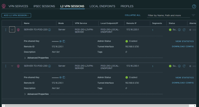
When both Layer 2 VPN Sessions are created the summary should look like this:
STEP 5〉 Link the local L2 Segment to the L2 VPN session
Now that the Layer 2 VPN Sessions are created I can link the (local) L2 Segment to this Layer 2 VPN Session that I want to stretch across all sites.
You also need to link the same Segment on the Hub side to all Layer 2 VPN Sessions for each SPOKE site.
STEP 6〉 Advertise VPN Endpoint addresses
When you configure the Layer Two VPN Local Endpoint peering IP address it is important that these also get advertised/redistributed to the physical network.
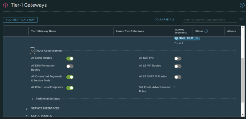
Tier–1 Gateway
Make sure you advertise the VPN Local Endpoints to the Tier-0 Gateway.
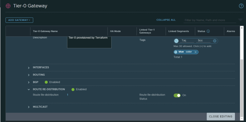
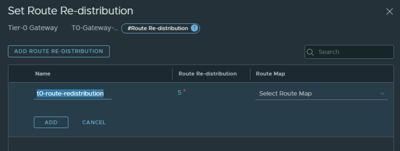
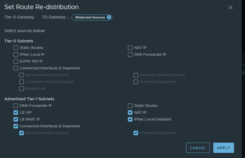
Tier–0 Gateway
Make sure you re-distribute the VPN Local Endpoints (on the Tier-1 Gateway) to the physical network.
L2-VPN Client side Spoke Configuration Steps
Pod–220 and Pod–230
STEP 1〉 Create VPN Services for IPSEC
The configuration for the client sites is both the same for Pod-220 and Pod-230.
Create a VPN Service for IPSEC:
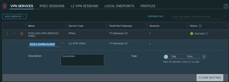
STEP 2〉 Create VPN Services for L2 VPN CLIENT
Create a VPN Service for L2 VPN SERVER:
You can also create a VPN Service for a Layer 2 SERVER, this will be done on the server-side, and here we create the L2 VPN CLIENT VPN Service.
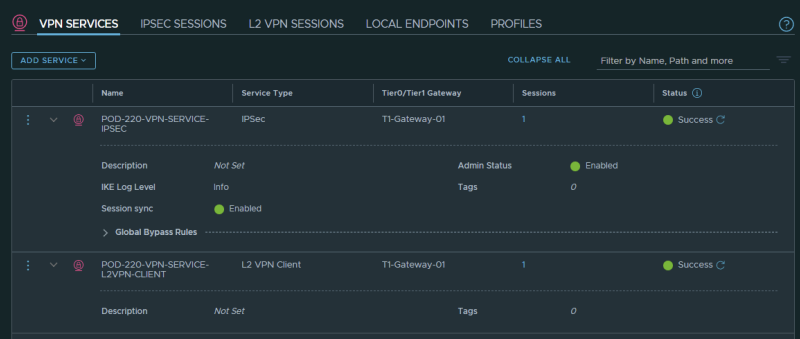
When both VPN Services are added this is the summary of how it should look like:
STEP 3〉 Create L2 VPN Session
Before you can create the L2 VPN Session on the client-side you need some information from the server-side in the form of a VPN configuration file.
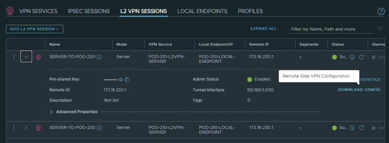
This information can be retrieved from the corresponding session you configured on the server-side:
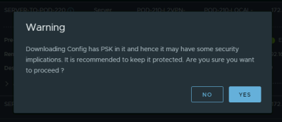
Before downloading the VPN configuration file you will get a warning message, Click Yes:
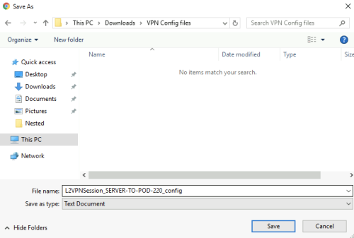
Make sure you download the file on a secure location:
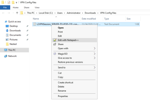
When the file is downloaded open it with your favorite text editor:
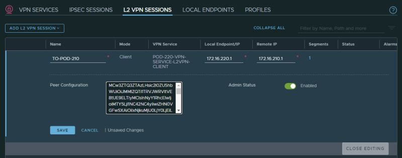
Locate the "peer code" and copy this to your clipboard as you will need this to create L2 VPN Session on the client-side.
Each client (HUB) site will have a unique VPN configuration file and unique "peer code"
Create a Layer 2 VPN Session towards Pod-210 (HUB) and make site you use the "peer code" from your clipboard:
When the Layer 2 VPN Session is created the summary should look like this:
This will automatically create/generate the Local Endpoints on the client-side for you.
STEP 4〉 Link the local L2 Segment to the L2 VPN session
Now that the Layer 2 VPN Sessions are created I can link the (local) L2 Segment to this Layer 2 VPN Session that I want to stretch across all sites.
STEP 5〉 Advertise VPN Endpoint addresses
When you configure the Layer Two VPN Local Endpoint peering IP address it is important that these also get advertised/redistributed to the physical network.
Tier–1 Gateway
Make sure you advertise the VPN Local Endpoints to the Tier-0 Gateway.
Tier–0 Gateway
Make sure you re-distribute the VPN Local Endpoints (on the Tier-1 Gateway) to the physical network.
L2-VPN Server-side HUB Verification
Pod–210
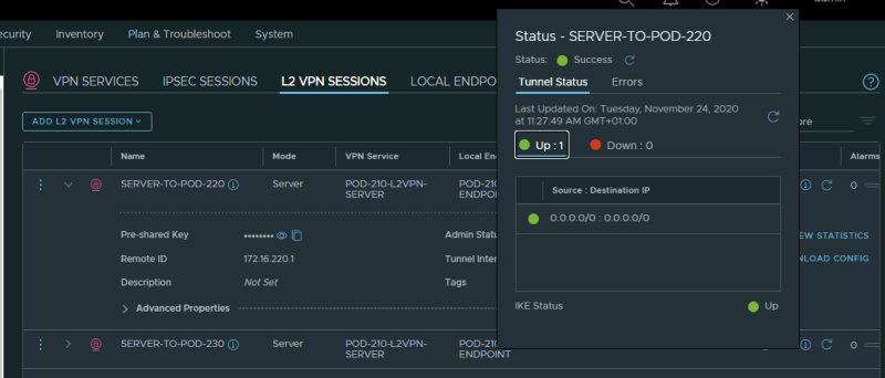
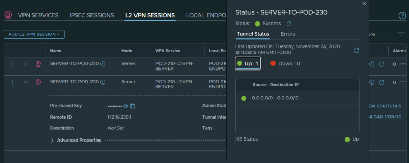
When you have performed the above steps correctly you can see the VPN tunnel as "Successful" with a green dot in the Sessions Configuration Section.
This is the output for the tunnel going to Pod-220 (from Pod-210):
This is the output for the tunnel going to Pod-220 (from Pod-210):
L2-VPN Client-side Spoke Verification
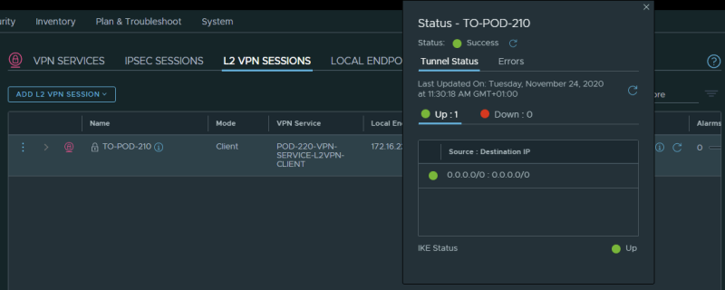
Pod–220
This is the output for the tunnel going to Pod-210 (from Pod-220):
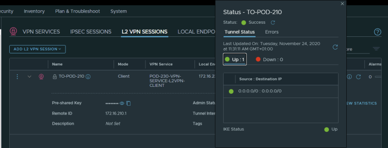
Pod–230
This is the output for the tunnel going to Pod-210 (from Pod-230):
Virtual Machine ping tests across the sites
In order to verify if I have real end-to-end connectivity between my Virtual Machine Workloads I have done some ping tests.
Pod–210
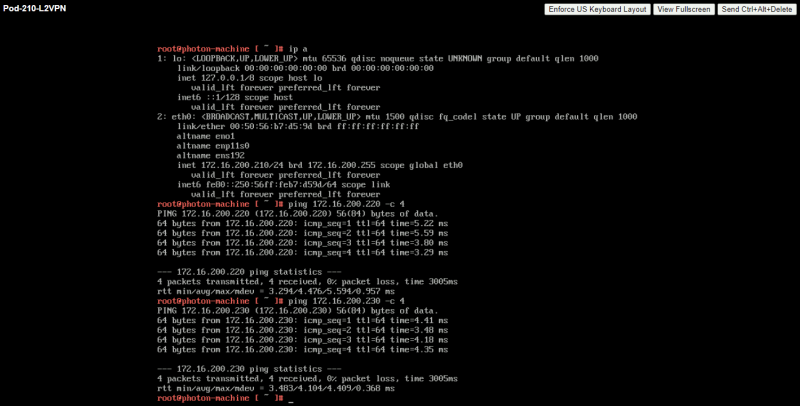
Here you can see my Virtual Machine located in Pod-210.
Here you can see a successful ping going from 172.16.200.210 (Pod-210) towards 172.16.200.220 (Pod-220) and 172.16.200.230 (Pod-230).
Pod–220
Here you can see my Virtual Machine located in Pod-220.
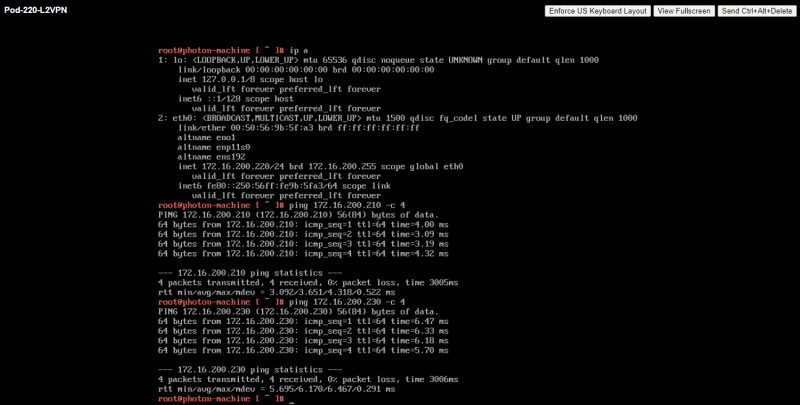
Here you can see a successful ping going from 172.16.200.220 (Pod-220) towards 172.16.200.210 (Pod-210) and 172.16.200.230 (Pod-230).
Pod–230
Here you can see my Virtual Machine located in Pod-230.
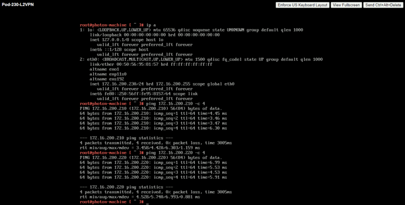
Here you can see a successful ping going from 172.16.200.230 (Pod-230) towards 172.16.200.210 (Pod-210) and 172.16.200.220 (Pod-220).
Conclusion
I have successfully demonstrated (together with Bal Birdy) that it is possible to set up a Layer 2 VPN Hub and Spoke network across multiple (private) clouds and stretched the same Layer 2 Subnet across all sites. The subnet 172.16.200.0/24 was successfully stretched and the following ping tests were successful.
| POD-210 = 172.16.200.210 | POD-220 = 172.16.200.220 | POD-230 = 172.16.200.230 | |
| POD-210 = 172.16.200.210 | ✓ (self) | ✓ | ✓ |
| POD-220 = 172.16.200.220 | ✓ | ✓ (self) | ✓ |
| POD-230 = 172.16.200.230 | ✓ | ✓ | ✓ (self) |
