ISP MPLS core design I (with OSPF and BGP) -- complete with config files and dynamips .net file
Due to my overall expierience with POC testing (Proof Of Concept testing) I wanted to build a solid basis to test some networking features in the future. I came up with designing and building a few template networks where I can do all of the testing that I am going to preform in the future. Of course some technologies needs a different approach and design, but this is my first that I can use to test most of the technologies that I am planning to look in to in the future. There are going to be more CORE designs explained but I will leave that for the future.
This is the long expected technical article of my ISP MPLS core design I with OSPF and BGP.
This design will have the following apects:
- 2 x P routers (the ISP core)
- 4 x PE routers (the provider edge)
- 4 x CE routers (the customer edge)
The complete design is designed in a way that if a device in the core fails, the traffic can still find it's destination due to the redundancy paths.
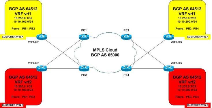
As we can see in the network diagrams there are 2 customers involved in this scenario (or LAB), customer YELLOW and customer RED.
The YELLOW (VRF1) customer and the RED (VRF2) customer both has 2 remote sites (allso called branche offices).
- YELLOW site 1 = VRF1-CE1
- YELLOW site 2 = VRF1-CE2
- RED site 1 = VRF2-CE1
- RED site 2 = VRF2-CE2
The physical diagram with the IP address information included is shown in the diagram below:

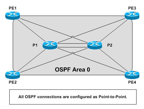
The IGP routing diagram:
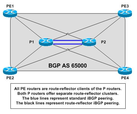
The BGP routing diagram:
The PE-CE routing diagram:
After creating the design I tested this in Dynamips/Dynagen. (The .net file can be found a little bit further in this article)
The BGP/OSPF information in the on the P(rovider) routers indicates that the actual core talks BGP with each other (EGP routing) and talks OSPF (IGP routing) with the PE's and with the P (Provider Edge Routers)
P1#sh ip bgp summary
BGP router identifier 10.0.0.1, local AS number 65000
BGP table version is 1, main routing table version 1
Neighbor        V    AS MsgRcvd MsgSent   TblVer  InQ OutQ Up/Down  State/PfxRcd
10.0.0.2        4 65000    2907    2907        1    0    0 09:40:48        0
P1#sh ip ospf neighbor

Neighbor ID     Pri   State           Dead Time   Address         Interface
10.0.1.4          0   FULL/  -        00:00:34    10.1.1.14       Serial1/3
10.0.1.3          0   FULL/  -        00:00:35    10.1.1.10       Serial1/2
10.0.1.2          0   FULL/  -        00:00:35    10.1.1.6        Serial1/1
10.0.1.1          0   FULL/  -        00:00:33    10.1.1.2        Serial1/0
10.0.0.2          0   FULL/  -        00:00:32    10.1.0.6        FastEthernet2/0
10.0.0.2          0   FULL/  -        00:00:32    10.1.0.2        FastEthernet0/0
P2#sh ip bgp summary
BGP router identifier 10.0.0.2, local AS number 65000
BGP table version is 1, main routing table version 1

Neighbor        V    AS MsgRcvd MsgSent   TblVer  InQ OutQ Up/Down  State/PfxRcd
10.0.0.1        4 65000    2920    2921        1    0    0 09:43:25        0

P2#sh ip ospf neighbor

Neighbor ID     Pri   State           Dead Time   Address         Interface
10.0.1.4          0   FULL/  -        00:00:36    10.1.2.14       Serial1/3
10.0.1.3          0   FULL/  -        00:00:37    10.1.2.10       Serial1/2
10.0.1.2          0   FULL/  -        00:00:35    10.1.2.6        Serial1/1
10.0.1.1          0   FULL/  -        00:00:38    10.1.2.2        Serial1/0
10.0.0.1          0   FULL/  -        00:00:35    10.1.0.5        FastEthernet2/0
10.0.0.1          0   FULL/  -        00:00:36    10.1.0.1        FastEthernet0/0
To verify if the yellow & red VRF (MPLS VPNs) are configured correctly and to verify if the interfaces are in the correct VRF's you can use the following commands:
PE1#sh ip vrf brief
  Name                             Default RD          Interfaces
  vrf1                             64512:1             Se1/2
  vrf2                             64512:2             Se1/3
PE2#sh ip vrf brief
  Name                             Default RD          Interfaces
  vrf1                             64512:1             Se1/2
  vrf2                             64512:2             Se1/3
PE3#sh ip vrf brief
  Name                             Default RD          Interfaces
  vrf1                             64512:1             Se1/2
  vrf2                             64512:2             Se1/3
PE4#sh ip vrf brief
  Name                             Default RD          Interfaces
  vrf1                             64512:1             Se1/2
  vrf2                             64512:2             Se1/3
The PE's are set up with MPLS Traffic Engineering tunnels to route the traffic. Offcourse there are multiple ways to achieve MPLS VPN routing, but the reason I chose for this method is that the WAN connections can be expensive for an ISP as they do not always have the budget for it. Traffic engineering enables the ISP to route network traffic in such a way that they can offer the best service to their users in terms of throughput, delay and redundancy.
To check if the traffic engineering tunnels are set up (both ways) in a proper way you can use the following commands:
PE1#sh mpls traffic-eng tunnels brief
Signalling Summary:
    LSP Tunnels Process:            running
    RSVP Process:                   running
    Forwarding:                     enabled
    Periodic reoptimization:        every 3600 seconds, next in 3367 seconds
    Periodic auto-bw collection:    disabled
TUNNEL NAME                      DESTINATION      UP IF     DOWN IF   STATE/PROT
PE1_t2                           10.0.1.2         -         Se1/1     up/up
PE1_t3                           10.0.1.3         -         Se1/1     up/up
PE1_t4                           10.0.1.4         -         Se1/1     up/up
PE2_t1                           10.0.1.1         Se1/0     -         up/up
PE3_t1                           10.0.1.1         Se1/1     -         up/up
PE4_t1                           10.0.1.1         Se1/0     -         up/up
Displayed 3 (of 3) heads, 0 (of 0) midpoints, 3 (of 3) tails
PE2#sh mpls traffic-eng tunnels brief
Signalling Summary:
    LSP Tunnels Process:            running
    RSVP Process:                   running
    Forwarding:                     enabled
    Periodic reoptimization:        every 3600 seconds, next in 3004 seconds
    Periodic auto-bw collection:    disabled
TUNNEL NAME                      DESTINATION      UP IF     DOWN IF   STATE/PROT
PE2_t1                           10.0.1.1         -         Se1/0     up/up
PE2_t3                           10.0.1.3         -         Se1/1     up/up
PE2_t4                           10.0.1.4         -         Se1/1     up/up
PE1_t2                           10.0.1.2         Se1/1     -         up/up
PE3_t2                           10.0.1.2         Se1/1     -         up/up
PE4_t2                           10.0.1.2         Se1/1     -         up/up
Displayed 3 (of 3) heads, 0 (of 0) midpoints, 3 (of 3) tails
PE3#sh mpls traffic-eng tunnels brief
Signalling Summary:
    LSP Tunnels Process:            running
    RSVP Process:                   running
    Forwarding:                     enabled
    Periodic reoptimization:        every 3600 seconds, next in 3001 seconds
    Periodic auto-bw collection:    disabled
TUNNEL NAME                      DESTINATION      UP IF     DOWN IF   STATE/PROT
PE3_t1                           10.0.1.1         -         Se1/1     up/up
PE3_t2                           10.0.1.2         -         Se1/1     up/up
PE3_t4                           10.0.1.4         -         Se1/1     up/up
PE1_t3                           10.0.1.3         Se1/1     -         up/up
PE2_t3                           10.0.1.3         Se1/1     -         up/up
PE4_t3                           10.0.1.3         Se1/1     -         up/up
Displayed 3 (of 3) heads, 0 (of 0) midpoints, 3 (of 3) tails
PE4#sh mpls traffic-eng tunnels brief
Signalling Summary:
    LSP Tunnels Process:            running
    RSVP Process:                   running
    Forwarding:                     enabled
    Periodic reoptimization:        every 3600 seconds, next in 2996 seconds
    Periodic auto-bw collection:    disabled
TUNNEL NAME                      DESTINATION      UP IF     DOWN IF   STATE/PROT
PE4_t1                           10.0.1.1         -         Se1/0     up/up
PE4_t2                           10.0.1.2         -         Se1/1     up/up
PE4_t3                           10.0.1.3         -         Se1/1     up/up
PE1_t4                           10.0.1.4         Se1/1     -         up/up
PE2_t4                           10.0.1.4         Se1/1     -         up/up
PE3_t4                           10.0.1.4         Se1/1     -         up/up
Displayed 3 (of 3) heads, 0 (of 0) midpoints, 3 (of 3) tails
The CE's are not VRF aware at all the only thing they have is OSPF routing information. Below I will do a simple ping test from the YELLOW site 1 LAN to the YELLOW site 2 LAN and I'll do the same for the RED VPN just to verify if everything is working correctly. I'll will also put in the traceroute so you can follow the atual path what the traffic is taking ... you can do some testing with a ping with a retry of 1000 and shutdown/rebboot 1 of the P routers or PE routers where the traffic is going trough just to check if the traffic is actually beeing rerouted ... you can try all of these fun things because I am making it your party :-)
Testing the YELLOW VPN for end-to-end connectivity ...
VRF1-CE1#ping 10.10.200.1
Type escape sequence to abort.
Sending 5, 100-byte ICMP Echos to 10.10.200.1, timeout is 2 seconds:
!!!!!
Success rate is 100 percent (5/5), round-trip min/avg/max = 164/220/300 ms

VRF1-CE1#traceroute 10.10.200.1
Type escape sequence to abort.
Tracing the route to 10.10.200.1
  1 192.168.1.2 40 msec 4 msec 28 msec
  2 10.1.2.1 [MPLS: Labels 34/36 Exp 0] 168 msec 196 msec 272 msec
  3 192.168.1.10 [AS 65000] [MPLS: Label 36 Exp 0] 64 msec 80 msec 132 msec
  4 192.168.1.9 [AS 65000] 268 msec *  200 msec
Testing the RED VPN for end-to-end connectivity ...
VRF2-CE1#ping 10.10.200.1
Type escape sequence to abort.
Sending 5, 100-byte ICMP Echos to 10.10.200.1, timeout is 2 seconds:
!!!!!
Success rate is 100 percent (5/5), round-trip min/avg/max = 184/233/304 ms

VRF2-CE1#traceroute 10.10.200.1
Type escape sequence to abort.
Tracing the route to 10.10.200.1
  1 192.168.1.2 8 msec 52 msec 72 msec
  2 10.1.2.1 [MPLS: Labels 34/29 Exp 0] 192 msec 124 msec 220 msec
  3 192.168.1.10 [AS 65000] [MPLS: Label 29 Exp 0] 64 msec 88 msec 224 msec
  4 192.168.1.9 [AS 65000] 236 msec *  100 msec
I hope this lab will help you understand the basic concepts of the MPLS VPN architecture and helps you understand the basics of the ISP core network. I also hope that this design can be the basis for you to also test some future technologies. The full configuration files can be found here below:
- P1.txt
- P2.txt
- PE1.txt
- PE2.txt
- PE3.txt
- PE4.txt
- VRF1-CE1.txt
- VRF1-CE2.txt
- VRF2-CE1.txt
- VRF2-CE2.txt
- all-config-files-mpls.rar
The .net file (to make this properly work you need to alter the paths towards the IOS files and the startup configs needed):
>> mplsv1.0.net
The actual network drawings can also be downloaden in PDF format:
>> Network Diagram - isp-mpls-vpn-v1.0.pdf
The IOS version that I used is "c7200-p-mz.124-25.bin" which I can not share due to copyright rules. I hope this post has been informative and fun to read and good luck with trying this at home!
If you have any questions or remarks please leave a comment or CONTACT me, I like to be challenged in what I do and I like compliments :-) it keeps me sharp and updated.
Take care and I wish you a happy Routing Experience ...