Logical Design components and the Logical Compute Design
So this is the part where we need to create Logical Designs. A typical virtual infrastructure has three main components. Compute, Network and Storage. For all these three components a Logical design needs to be created. All three of these logical design components will have to be described in the overall architectural design document. The focus dept however may be different depends on the VCDX track you are doing. If you do VCDX-DCV the focus will have to be more on compute and storage using the vSphere components and if you do VCDX-NV the focus has to be more on the network. This makes sense right?
This article is part of my VCDX blog article series that can be found here.
Next to these three main components Security, Backup and Availability and Management is important as well.
In this article we are going to talk about Defining a Logical Compute Design.
What does a logical design means and what does it include?
From my previous blog posts we can recall that a logical design is a high level abstract design without specifying any solutions of products.
And therefore in a logical Compute design we are going to include the following:
1) Aggregate CPU capacity (this is typically expressed in Gigahertz (Ghz))
2) Aggregate RAM capacity (this is typically expressed in Gigabyte (GB) and sometimes in Terrabytes (TB))
3) Socket-to-core ratios and target core-to-VM rations
4) A description of the expandability of the logical compute design
NOTE AGAIN: We do NOT include and particular products, brands, solutions or models in here.
You may specify specific technologies. An example of this is that you can say that the CPU should support hardware virtualization elements. Here you say that the logical network design needs to have a specific function but you are NOT saying that it should support Intel nested page tables as this would be too specific and belongs in the physical design.
I have not listed the following elements into this article (as I will discuss this later in another article) are:
1) The number of clusters that we will use
2) The cluster size (per cluster)
3) The use of resource pools
4) Use of a separate management cluster to host the vSphere infrastructure components
These will be discussed later to have a better understanding of the impact on several design choices.
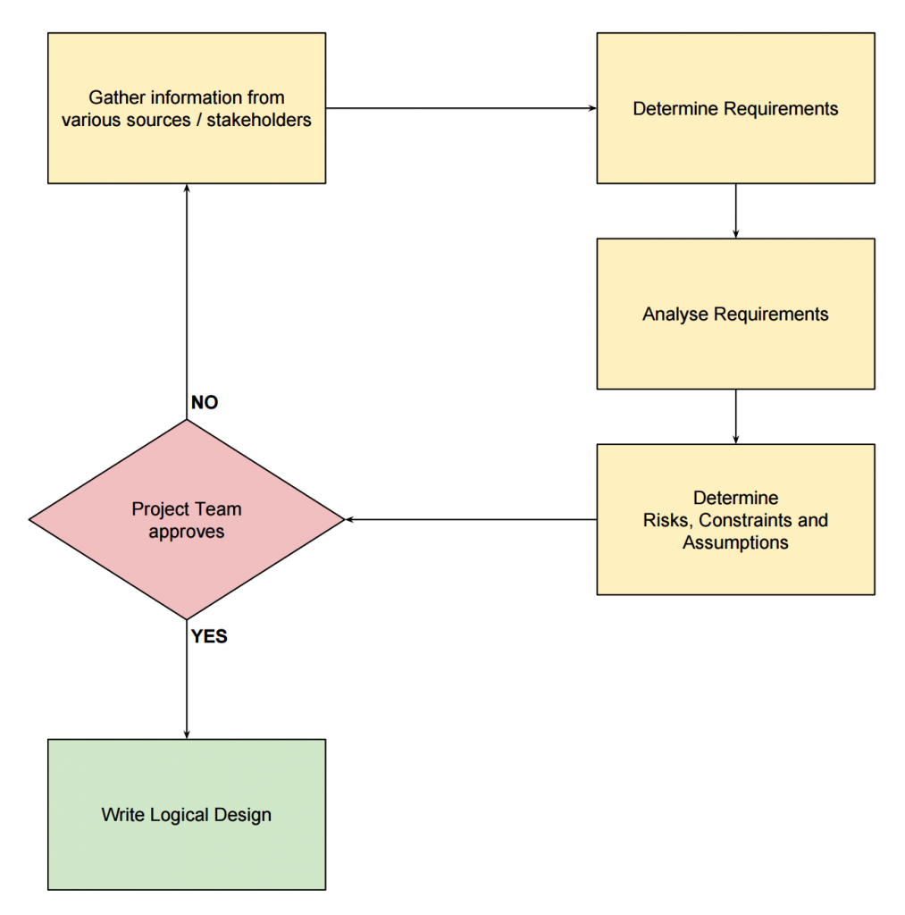
How do we determine what aggregate values we specify? This is done during the requirement analysis when the requirements are already known. This information was obtained during the information gathering process.
Here you saw this drawing:
When we determine the requirement there need to be a (functional) requirement that specify a certain amount of CPU capacity and RAM capacity. These aggregates are driven straight out of the requirement analysis based in data provided from tools that asses the current environment (brownfield) or from information gathered from stakeholders when the environment is going to be newly build (Greenfield).
Tools that asses a current environment where discussed in this blog post.
The calculation in determining the logical design values are to:
1) Aggregate the requirements - driven by the functional requirements and defined in the requirement analysis from information gathered in that phase
2) Desired maximum utilisation thresholds - how far can the environment be pushed in terms of utilisation, 70%, 80% or maybe 90%?
3) Anticipated growth (if there is any)
4) Anticipated virtualization benefit (if there is any) - when we talk about aggregated RAM capacities there is a potential virtualization benefit that VMWare vSphere offers with several memory sharing technologies.
With the above values in mind I think its good to show an example compute logical design to understand how this should look like. It is good to see the numbers that are used in this example and explain how we got there.
The example that I will use is taken from the Cloud Infrastructure Architecture Case Study - White Paper by VMware.
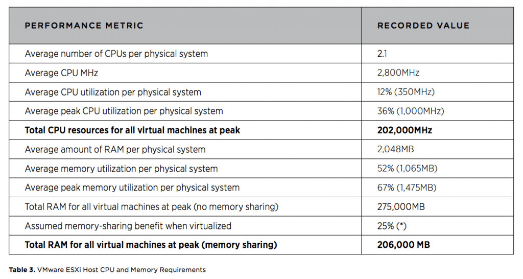
 This table contains information that was gathered during an assessment.
VMWare Capacity Planner Tool was used to gather this data.
The information that is gathered in this table is the:
CPU:
1) Average number of CPUs per physical system
2) Average CPU MHz
3) Average CPU utilisation per physical system
4) Average peak CPU utilisation per physical system Total CPU resources for all virtual machines at peak
The 202,000 Mhz of CPU cycles is your functional requirement. The environment needs to be able to drive at least 202,000 Mhz in total. This number is divided across multiple VM's of course.
RAM:
1) Average amount of RAM per physical system
2) Average memory utilisation per physical system
3) Average peak memory utilisation per physical system
4) Total RAM for all virtual machines at peak (no memory sharing)
5) Assumed memory-sharing benefit when virtualized (*)
Total RAM for all virtual machines at peak (memory sharing)
The * in #5 is to indicate that this number is deliberately is kept low because it is assumed in the assumptions that Guest operating systems will leverage large page tables. This typically results in a lower memory sharing benefit.
The 206,000 MB of RAM is your functional requirement. The environment needs to be able to drive at least 206,000 MB of RAM (or 206 TB) in total. This number is divided across multiple VM's of course.
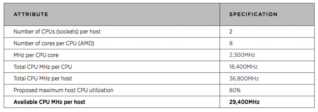
How do we determine how the logical compute design is going to look like? In the above example the numbers where determined in the design process by using a tool. We can run some what-of scenarios (depending on the tool you use) to come to a so called "sweet spot" which is the number of sockets per host, the number or cores per CPU.
CPU: In this particular example hosts are chosen with the ability to have two CPU sockets per host with 8 cores per CPU with the speed of 2300 Mhz per core. If we calculate the total Mhz per CPU we het 8 x 2300 = 18,400 Mhz per CPU. So if we have two sockets this means 18,400 x 2 = 36,800 Mhz per host. They take 80% as the maximum utilisation which means that the available CPU speed per host will be 36,800 - 20% = 29,440 Mhz per host available.
The 29,440 Mhz is the maximum amount of CPU cycles any host should be able to contribute.
 RAM:
The total RAM per host is set to 96,000 MB (or 96 TB).
With the same 80% utilisation the available RAM per host will be 96,000 - 20% = 76,800MB (or 76,8 TB) RAM available per host.
The 76,800MB is the maximum amount of RAM any host should be able to contribute.
 From the above information we can derive how many hosts are required to come to the total 202,000 Mhz of CPU and 206,000 MB of RAM.
76,800 MB x 3 = 230,400 29,440 Mhz x 7 = 206,080 Mhz
 Because the of the number of CPU cycles required require to have 7 hosts we need to select a minimum of 7 hosts to satisfy this requirement.
When we take growth (of 20%) and availability (N+1) into account.
7 hosts + 20% = 8,4 = 9 hosts + 1 = 10
 Other factors can influence this requirements.
When we have two managing parties for example ... this may need to be spread into two different clusters or groups of servers and with that the growth and availability changes.
With creating the logical compute design it is important to determine impact of the choices made. This can only be done by relating areas with each other and examining these.
Example#1: What effect does aggregated CPU capacity has on the design? What components / areas are impacted with the change of aggregated CPU?
1) The ability of the design to satisfy the requirements - If we do not specify a large enough value for aggregated CPU capacity the design will not be able to satisfy the given functional requirement 2) Financial constraint - specifying too much CPU capacity will have a financial impact
Example#2: What effect does aggregated RAM capacity has on the design? What components / areas are impacted with the change of aggregated RAM?
1) The ability of the design to satisfy the requirements
2) Licensing - vSphere 5 + 6 adds a memory tier in the licensing structure
3) Financial constraint - over provision RAM could result in higher cost or RAM and licensing
Example#3: What does socket-to-core rations affect? Does it matter if we specify 2 sockets with 4 cores, or 1 socket with 8 cores?
1) Licensing - vSphere licences per socket
2) Target VM-to-Core-Ratios - the amount of VM's that are hosted on a particular physical CPU / core If this is too high how will this be affected in the designs performance requirements that meets SLA/SLO's.
3) Physical Form Factors - If we specify that we want 4 sockets with 4 cores each, we need to have hosts that offer this capacity and some blades may not support this which makes these blade models not usable
Example#4: What affect has expandability?
1) The ability of the design to satisfy the requirements (with future growth into mind) - if you don't specify enough expandability the environment can't grow
2) Financial constraint - based on the product you specify to use this can impact financial constraints
By listing all these relationship impacts down and approaching this with a question / answer form forces you to think about the relationships and impact.
Another way to do this and that has my preference is to use Mindmaps. With mindmaps you can specify different elements and point out the impact per element in a graphical way.
I am using Xmind for the Mac for this.
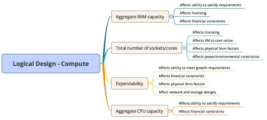
Below you will see an example of how impact is determined with the Logical Compute Design with the use of a mindmap:
 This mindmap shows the relationships between topics and ideas.
A mindmap is a great way of exploring relationships in a design.
In this mindmap example I have used the 4 examples used above (CPU, RAM, Sockets/cores, Expandability). With taking this approach you could go into several of multiple layers. When every time something changes with different options the impact will change based on the chosen option.
This article is part of my VCDX blog article series that can be found here.
