Transport Nodes
A transport node within NSX is a server that can be either physical or virtual that is responsible for “transporting” network traffic.
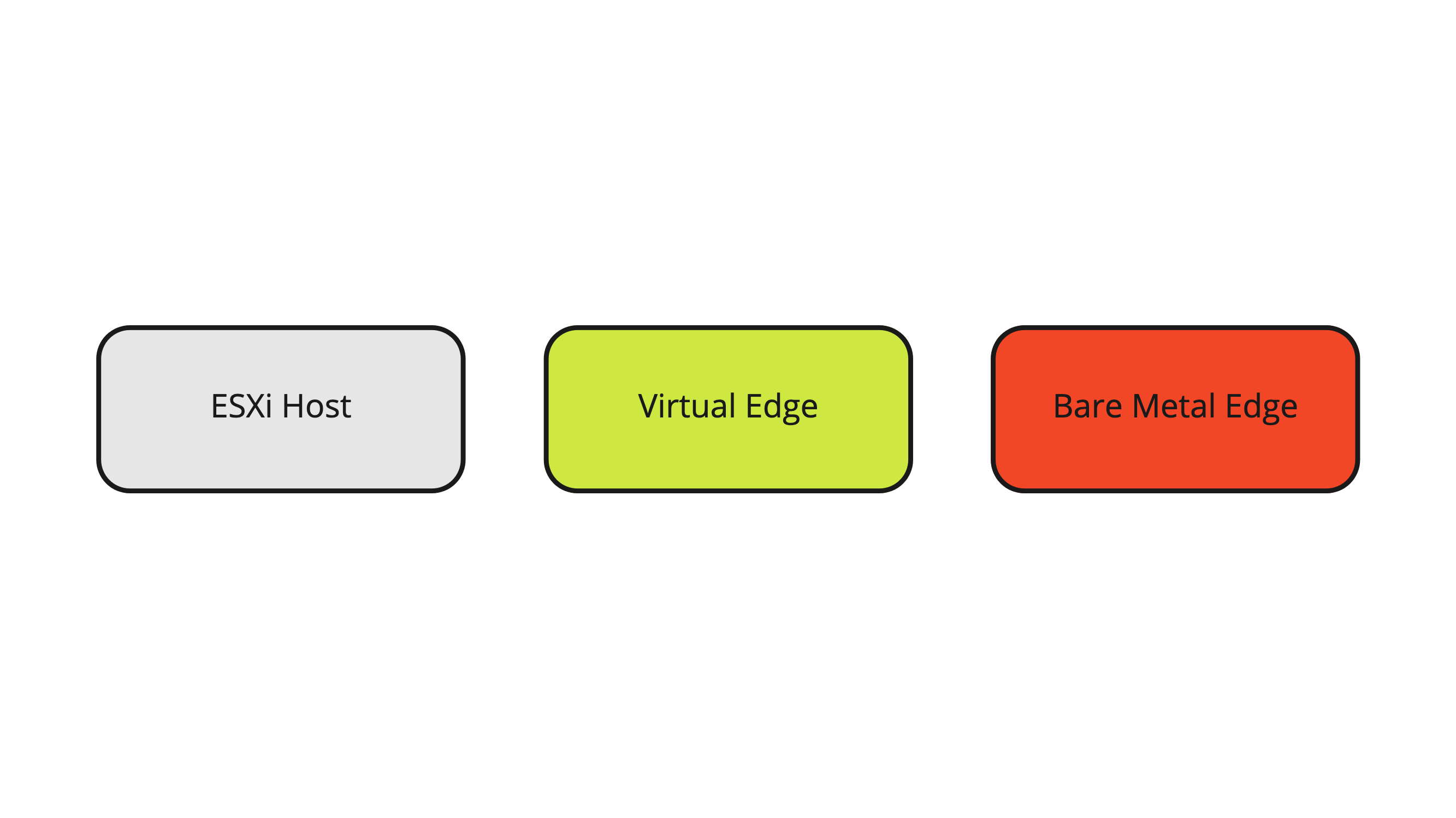
Figure 13 illustrates the different types of transport nodes. The transport nodes are divided into two categories:
- Host Transport Nodes
- This can be either a Bare Metal Server, ESXi Host, or KVM host.
- The ESXi and KVM hosts are used as Hypervisors to host Virtual Machines.
- Edge Transport Nodes
- This can be either a Virtual Edge or a Bare Metal Edge.
- This can be either a Bare Metal Server, ESXi Host, or KVM host.
Figure 13:
Bare Metal Server
A Bare Metal Transport Node Server is a server that is not hosting any Virtual Machines and is not a Hypervisor.
This server is a server with a regular operating system (for example, Windows Server). When this server becomes a transport node, you will install NSX bits on the server so that this server can be enabled for supported NSX services (for example to be part of an overlay network provided by NSX).
ESXi Server
The ESXi server is VMware’s Hypervisor that is primarily used to host VMware Virtual Machines. When this server becomes a transport node, you will install NSX bits on the server so that this server can be enabled for supported NSX services (for example to be part of an overlay network provided by NSX).
The main difference between the Bare Metal Server and the ESXi server is that the supported NSX services (for example overlay networks) are now provided to the Virtual Machines hosted by the ESXi server.
KVM Server
The KVM Server is not in scope here, but the KVM server can be compared with the ESXi host in terms of functionality and therefore it is also a Hypervisor that offers the capability to host KVM-based Virtual Machines.
Edge Transport Nodes
The Edge Transport Nodes (Virtual or Bare Metal) are used to provide network services. They also enable North/South network connectivity. The North/South network connectivity is processed by Virtual Gateways that are hosted inside the Edge Transport Nodes.
The (virtual) Tier-0 Gateway is responsible for all North/South network connectivity from the NSX overlay networks to the Physical Network and is responsible to offer network services.
The (virtual) Tier-1 Gateway is connected to a Tier-0 Gateway and is responsible to offer network services. It is possible to have multiple Tier-1 Gateways connected to a single Tier-0 Gateway.
In the NSX Networking section, I will explain more about the Tier Gateways and Segments and the relation between these objects.
Transport Nodes 〈cluster〉 Design
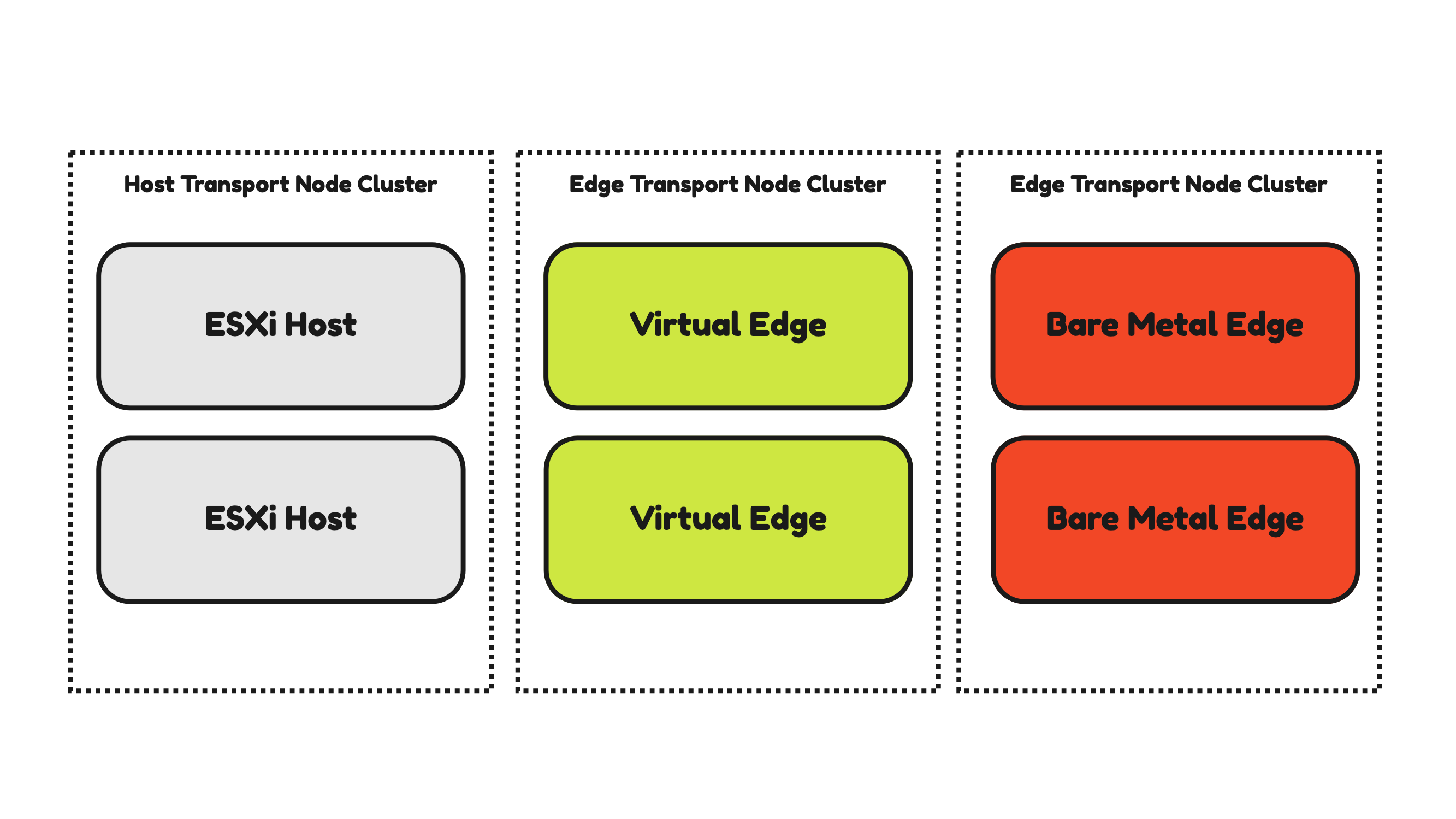
For availability and recoverability purposes and configuration consistency, it is possible to configure the Transport Nodes in a cluster.
The ESXi Host Transport Nodes are typically already configured in a cluster on the vSphere level. This means that a collection of ESXi servers is already configured on the vCenter Server as a vSphere cluster. This cluster is inherited by NSX when you want to enable NSX on all the ESXi servers in the cluster. A Host Transport Node Profile is used to configure the ESXi hosts part of a vSphere Cluster.
To form a cluster for the Edge Transport Nodes an Edge Cluster needs to be created inside NSX. It is NOT possible to mix Virtual and Bare Metal Edges within the same Edge cluster.
Figure 14:
ESXi Host Transport Nodes
From a Physical (physical NICs) and Virtual Network level (VDS), it is possible to have different designs that result in different configurations. All different types of design/configurations will have its pros and cons. In this section, I will discuss a few of these configurations and why they can be better compared to the others.
Host Transport Node VSS and VDS and pNIC Design
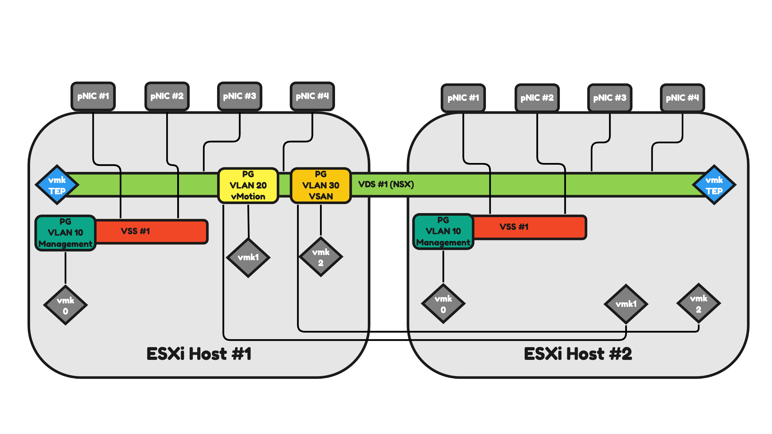
Figure 15 will illustrate two ESXi hosts that have a 2-pNIC (two physical Network Interface Cards) configuration. Because the ESXi hosts are part of a vSphere Cluster they have the option to make use of a Virtual Distributed Switch (VDS).
The VDS is a shared vCenter Server (or vSphere) object that all ESXi Servers in the cluster can make use of.
Let’s focus on one ESXi host and the 2-pNICs for now as the second one will work and operate the same.
ESXi host #1:
- The ESXi host makes use of one (shared) VDS.
- The ESXi host has two physical Network Interfaces that are mapped to the (shared) VDS.
- The VDS has three Distributed Virtual Port Groups (DVPG) with different VLANS and different VMkernel (vmk) interfaces mapped for a DVPG (and VLAN).
- The DVPGs are shared so ESXi host #2 will also have access to them for its own (local) vmk interfaces.
- VLAN 10 = ESXi Management Network Traffic.
- VLAN 20 = vMotion Network Traffic.
- VLAN 30 = VSAN Network Traffic.
- The ESXi host has the NSX Tunnel Endpoint Interface (TEP) configured as the host is configured as an NSX Transport node.
- The TEP interface is an interface (just like the vmk interfaces) local to the ESXi host.
- The number of TEP interfaces used depends on the Uplink Profile configuration.
- In this case, only one TEP interface is configured.
- The TEP interface will use a dedicated VLAN (that is not on the figure)
Pros:
- You can argue that you have fewer objects to manage (only one VDS) and therefore management is simpler.
Cons:
- In a configuration like this, all network traffic (Management, vMotion, VSAN, NSX Uplink, NSX Overlay) will use the same(two) interfaces.
- In this case, you need additional configuration to have some form of traffic prioritization as VSAN can be heavy on traffic consumption and you do not want to lose the management of your host when VSAN is pumping a huge amount of VSAN across the (shared) interfaces).
Figure 15:
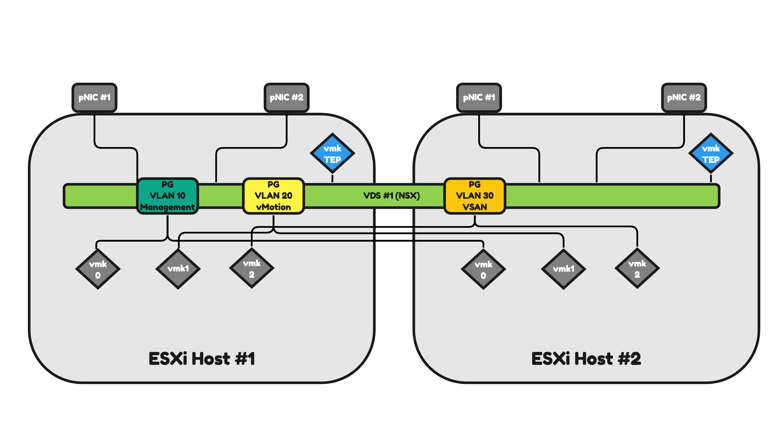
Figure 16 will illustrate two ESXi hosts that have a 4-pNIC (two physical Network Interface Cards) configuration.
The only difference with Figure 15 is the number of pNICs. This means that the network traffic can now be spread across four pNICs instead of two, offering a better way to share the network traffic load and send/process more traffic (throughput) than it would be possible with two interfaces.
Pros:
- You can argue that you have fewer objects to manage (only one VDS) and therefore management is simpler.
- You have additional interfaces available to process more traffic.
Cons:
- In a configuration like this, all network traffic (Management, vMotion, VSAN, NSX Uplink, NSX Overlay) will use the same(two) interfaces.
- In this case, you need additional configuration to have some form of traffic prioritization as VSAN can be heavy on traffic consumption and you do not want to lose the management of your host when VSAN is pumping a huge amount of VSAN across the (shared) interfaces).
- You have more interfaces, and this will introduce an additional cost.
Figure 16:
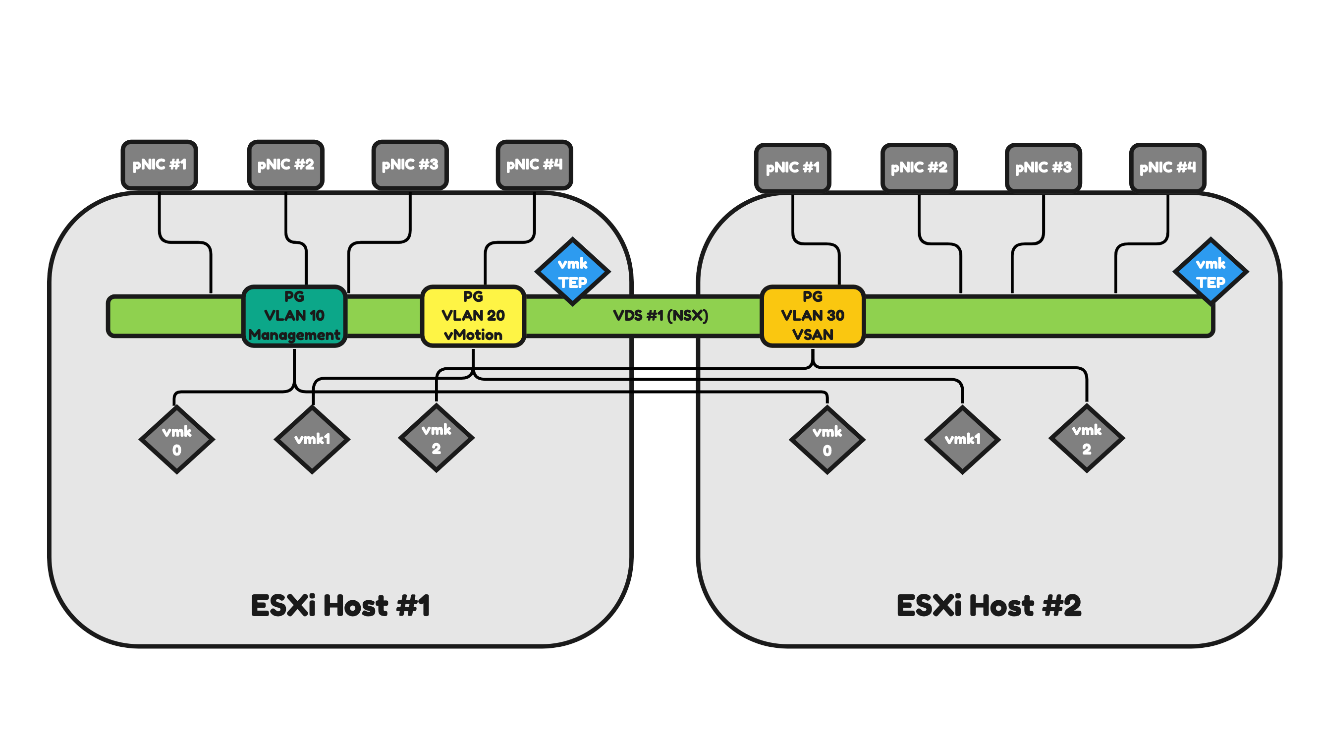
Figure 17 will have the same amount of pNICS as in Figure 16. The difference now is that I will use two dedicated interfaces that I will map to a dedicated (local) vSphere Standard Switch (VSS).
Let’s focus on one ESXi host and the 4-pNICs for now as the second one will work and operate the same.
ESXi host #1:
- The ESXi host makes use of one (shared) VDS.
- The ESXi host makes use of one (local) VSS.
- The ESXi host has two physical Network Interfaces that are mapped to the (shared) VDS.
- The ESXi host has two physical Network Interfaces that are mapped to the (local) VSS.
- The VDS has two Distributed Virtual Port Groups (DVPG) with different VLANS and different VMkernel (vmk) interfaces mapped for a DVPG (and VLAN).
- The DVPGs are shared so ESXi host #2 will also have access to them for its own (local) vmk interfaces.
- VLAN 20 = vMotion Network Traffic.
- VLAN 30 = VSAN Network Traffic.
- The VSS has one Virtual Port Group (PG) with a different VLAN and a different VMkernel (vmk) interface mapped for a PG (and VLAN).
- VLAN 10 = ESXi Management Network Traffic.
- The ESXi host has the NSX Tunnel Endpoint Interface (TEP) configured as the host is configured as an NSX Transport node.
- The TEP interface is an interface (just like the vmk interfaces) local to the ESXi host.
- The number of TEP interfaces used depends on the Uplink Profile configuration.
- In this case, only one TEP interface is configured.
- The TEP interface will use a dedicated VLAN (that is not on the figure)
Pros:
- You have additional interfaces available to process more traffic.
- The ESXi Management traffic is using two dedicated pNICs.
Cons:
- You can argue that you have more objects to manage (one VSS and one VDS) and therefore management is harder.
- In a configuration like this, all network traffic (vMotion, VSAN, NSX Uplink, NSX Overlay) will use the same(two) interfaces.
- In this case, you need additional configuration to have some form of traffic prioritization as VSAN can be heavy on traffic consumption and you do not want to lose the vMotion capability of your host when VSAN is pumping a huge amount of VSAN across the (shared) interfaces).
- You have more interfaces, and this will introduce an additional cost.
Figure 17:
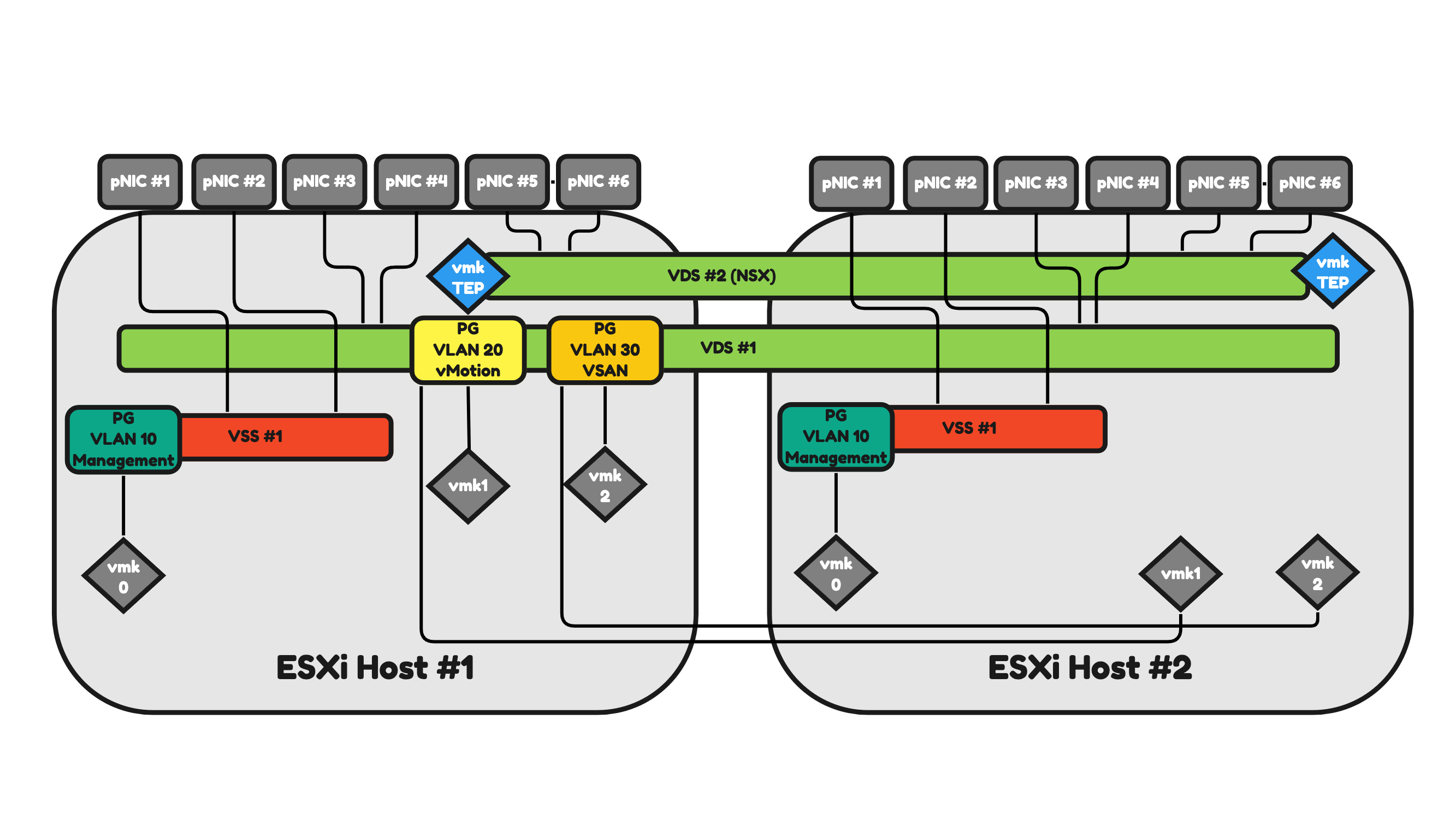
In Figure 18 I am adding two additional pNICs (making the total of interfaces now 6) per ESXi host. I am also adding an additional VDS. With this I am dedicating different pNIC pairs to different Virtual Switches.
Let’s focus on one ESXi host and the 6-pNICs for now as the second one will work and operate the same.
ESXi host #1:
- The ESXi host makes use of two (shared) VDSs.
- One VDS is dedicated to NSX uplink and overlay network traffic.
- One VDS is dedicated to vMotion and VSAN network traffic.
- The ESXi host makes use of one (local) VSS.
- This VSS is dedicated to ESXi management network traffic.
- The ESXi host has two physical Network Interfaces that are mapped to the (shared) VDS for NSX.
- The ESXi host has two physical Network Interfaces that are mapped to the (shared) VDS for vMotion and VSAN.
- The ESXi host has two physical Network Interfaces that are mapped to the (local) VSS for ESXi Management.
- The NSX VDS has no Distributed Virtual Port Groups (DVPG) but has the NSX Tunnel Endpoint Interface (TEP) configured as the host is configured as an NSX Transport node.
- The TEP interface is an interface (just like the vmk interfaces) local to the ESXi host.
- The number of TEP interfaces used depends on the Uplink Profile configuration.
- In this case, only one TEP interface is configured.
- The TEP interface will use a dedicated VLAN (that is not on the figure)
- The other VDS has two Distributed Virtual Port Groups (DVPG) with different VLANS and different VMkernel (vmk) interfaces mapped for a DVPG (and VLAN).
- The DVPGs are shared so ESXi host #2 will also have access to them for its own (local) vmk interfaces.
- VLAN 20 = vMotion Network Traffic.
- VLAN 30 = VSAN Network Traffic.
- The VSS has one Virtual Port Group (PG) with a different VLAN and a different VMkernel (vmk) interface mapped for a PG (and VLAN).
- VLAN 10 = ESXi Management Network Traffic.
Pros:
- You have additional interfaces available to process more traffic.
- The ESXi Management traffic is using two dedicated pNICs.
- The NSX (NSX Uplink, NSX Overlay) traffic is using two dedicated pNICs.
- In a configuration like this, the network traffic will be spread across different dedicated pNICs and Virtual Switches.
- In this case, you still need additional configuration to have some form of traffic prioritization as VSAN can be heavy on traffic consumption and you do not want to lose the vMotion capability of your host when VSAN is pumping a huge amount of VSAN across the (shared) interfaces).
Cons:
- You can argue that you have more objects to manage (one VSS and two VDSs) and therefore management is harder.
- You have more interfaces, and this will introduce an additional cost.
Figure 18:
⚠️ As you can see you can have different configurations when it comes to the number of pNICs and Virtual Switches (VSSs and VDSs) and the way you want your network traffic to be distributed. I have only highlighted a few just to give you an idea of what is possible and why.
Edge Transport Nodes
An Edge Transport Node can either be Virtual or Bare Metal.
In this section, I will discuss the most common way of designing and implementing of both form factors.
Virtual Edge Transport Nodes
A Virtual Edge is typically hosted as a Virtual Machine (VM) on ESXi hosts. Like every other Virtual Machine, the Virtual Edge also makes use of the Virtual Port Groups offered by the Virtual Switch (VSS or VDS).
An Edge VM typically has four Virtual Network Interface Cards (vNICs). And these vNICs are mapped to a Port Group to allow the correct transport of traffic coming from these Edge VMs.
An Edge VM is responsible for North/South connectivity, overlay network routing, and various other network services supported by NSX. All these different traffic types are using different VLANs, pNIC and vNIC interfaces. The way how this works depends on the way you design it.
The required VLANs for an Edge Transport Node to operate are:
- Management VLAN (10)
- Host TEP VLAN (40)
- Edge TEP VLAN (50)
- BGP Uplink VLAN #1 (100)
- BGP Uplink VLAN #2 (200)
In Figure 19 I am hosting two Edge VMs on a single ESXi host. In this case, this ESXi host is also an NSX (Host) Transport Node. This ESXi host has two pNICS.
⚠️ An Edge VM can also be hosted on an ESXi host that is not an NSX Transport node.
This means that all the traffic that is required for the Edge VM to fully operate needs to be shared/split/divided across these two Physical Network Interface Cards. The way how this is done in Figure 19 is that I have created three Port Groups:
- Management Port group (10)
- Trunk Port Group A (all VLANs)
- Trunk Port Group B (all VLANs)
Table 3 will provide you with an overview of how the traffic will be flowing.
Table 3» Virtual Edge Traffic Mapping on a 2–pNIC Host 〈Figure 19〉
| Property | Port Group | Host pNIC | Edge vNIC |
|---|---|---|---|
| Management Traffic | PG VLAN 10 Management | pNIC #1 (active) pNIC #2 (standby) |
vNIC #1 |
| Host TEP Traffic | N/A | pNIC #1 (active) pNIC #2 (standby) |
N/A |
| Edge TEP Traffic | PG Trunk A PG Trunk B |
pNIC #1 (active) pNIC #2 (active) |
vNIC #1 vNIC #2 |
| BGP Uplink 1 Traffic | PG Trunk A | pNIC #1 (active) pNIC #2 (standby) |
vNIC #2 |
| BGP Uplink 2 Traffic | PG Trunk B | pNIC #1 (standby) pNIC #2 (active) |
vNIC #3 |
Figure 19:
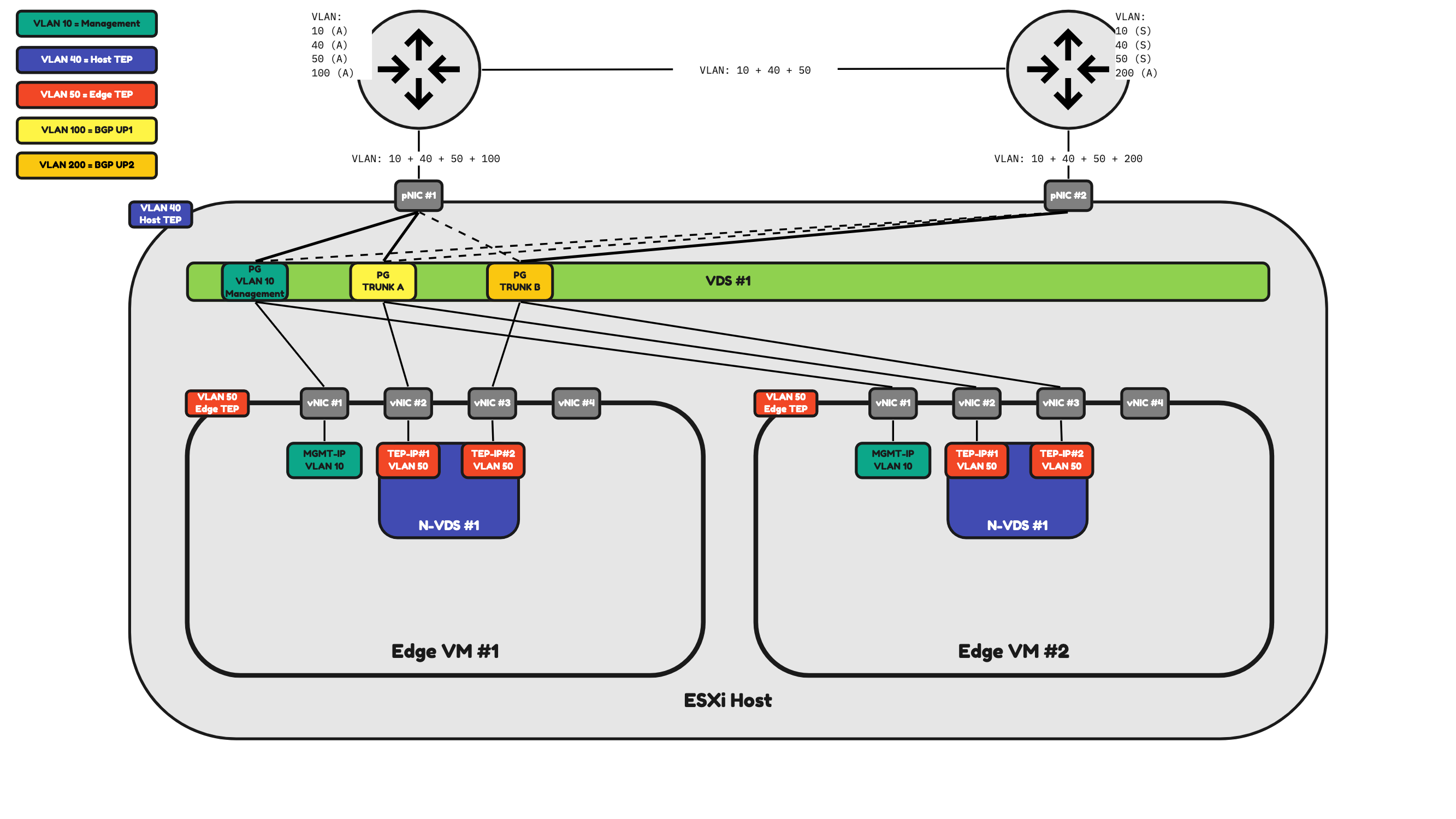
You can see here the way how the traffic is distributed here, and with only two pNICs to work with on the ESXi server level this is the most optimal way of doing it. So, in this case (Figure 19) Both Edge VMs share the same Port Groups and the same pNICs.
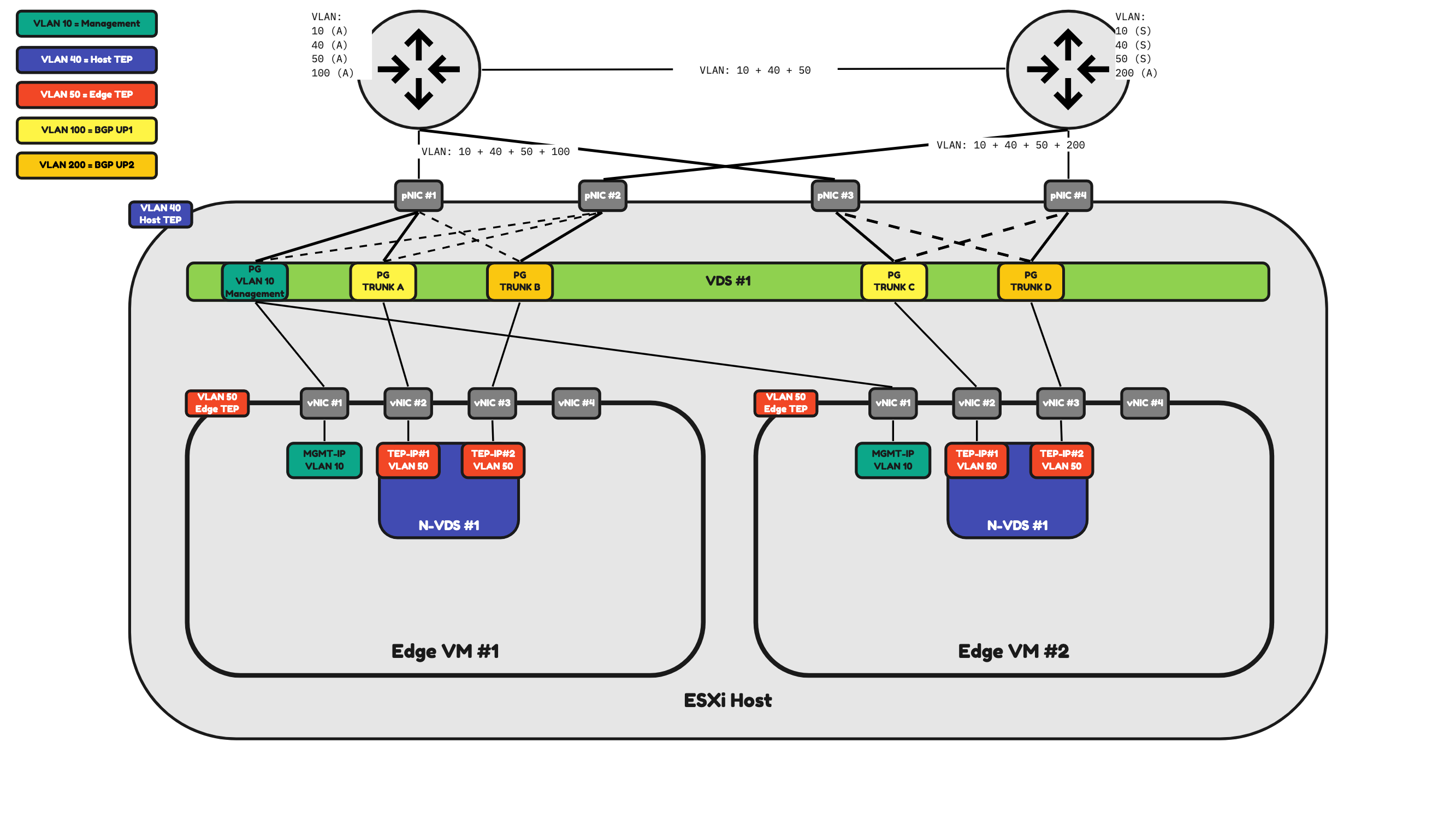
In Figure 20 I have added two additional pNICs to the ESXi host and I have also added two additional Port Groups. With this design, I can now dedicate two physical Interfaces (pNIC #1 and pNIC #2) to the NSX Uplink and Overlay network traffic coming and going to Edge VM #1 and two other physical Interfaces (pNIC #3 and pNIC #4) to the NSX Uplink and Overlay network traffic coming and going to Edge VM #2.
Figure 20:
Bare Metal Edge Transport Nodes
A Bare Metal Edge is typically a physical server.
A Bare Metal Edge can have as many pNICs as you want. And these pNICS will process the traffic based on your configuration.
Just like an Edge VM, a Bare Metal Edge is also responsible for North/South connectivity, overlay network routing, and various other network services supported by NSX. All these different traffic types are also using different VLANs and depending on the amount of pNICs different pNICs as well. The way how this works depends on the way you design it.
The required VLANs for an Edge Transport Node to operate are:
- Management VLAN (10)
- Edge TEP VLAN (50)
- BGP Uplink VLAN #1 (100)
- BGP Uplink VLAN #2 (200)
In Figure 21 I am hosting two Bare Metal Edges and these Edges have two physical Network Interface Cards.
This means that all the traffic that is required for the Bare Metal Edges to fully operate needs to be shared/split/divided across these two Physical Network Interface Cards.
Table 4 will provide you with an overview of how the traffic will be flowing.
ADD TABLE 4
Table 4» 2–pNIC Bare Metal Edge Traffic Mapping 〈Figure 21〉
| Property | Host pNIC |
|---|---|
| Management Traffic | pNIC #1 (active) pNIC #2 (standby) |
| Edge TEP Traffic | pNIC #1 (active) pNIC #2 (active) |
| BGP Uplink 1 Traffic | pNIC #1 |
| BGP Uplink 2 Traffic] | pNIC #2 |
⚠️ Network traffic can either be sent using both interfaces (active/active) or only using one active interface and the other one as the standby (active/standby). This all depends on how you would configure the Uplink Profiles, and this all depends on your (customer) requirements.
Figure 21:
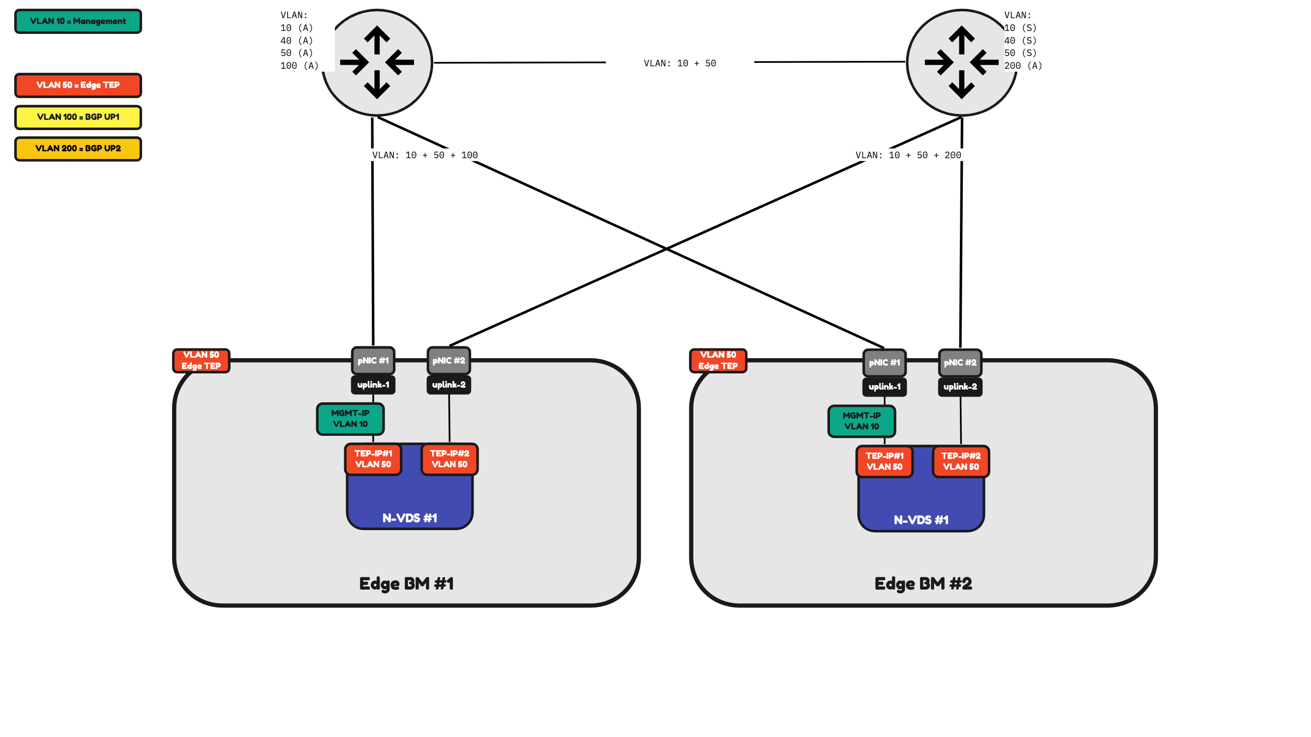
Because I only have two physical interfaces on the Bare Metal Edge to process network traffic this means that all NSX traffic (management, overlay and BGP uplink traffic) will be sent across these interfaces.
In Figure 22 I have added two additional pNICs to Bare Metal Edge. The configuration is still the same as the Bare Metal Edge in Figure 21. But I have the flexibility to have dedicated Management Interfaces which is shown in Figure 23.
Figure 22:
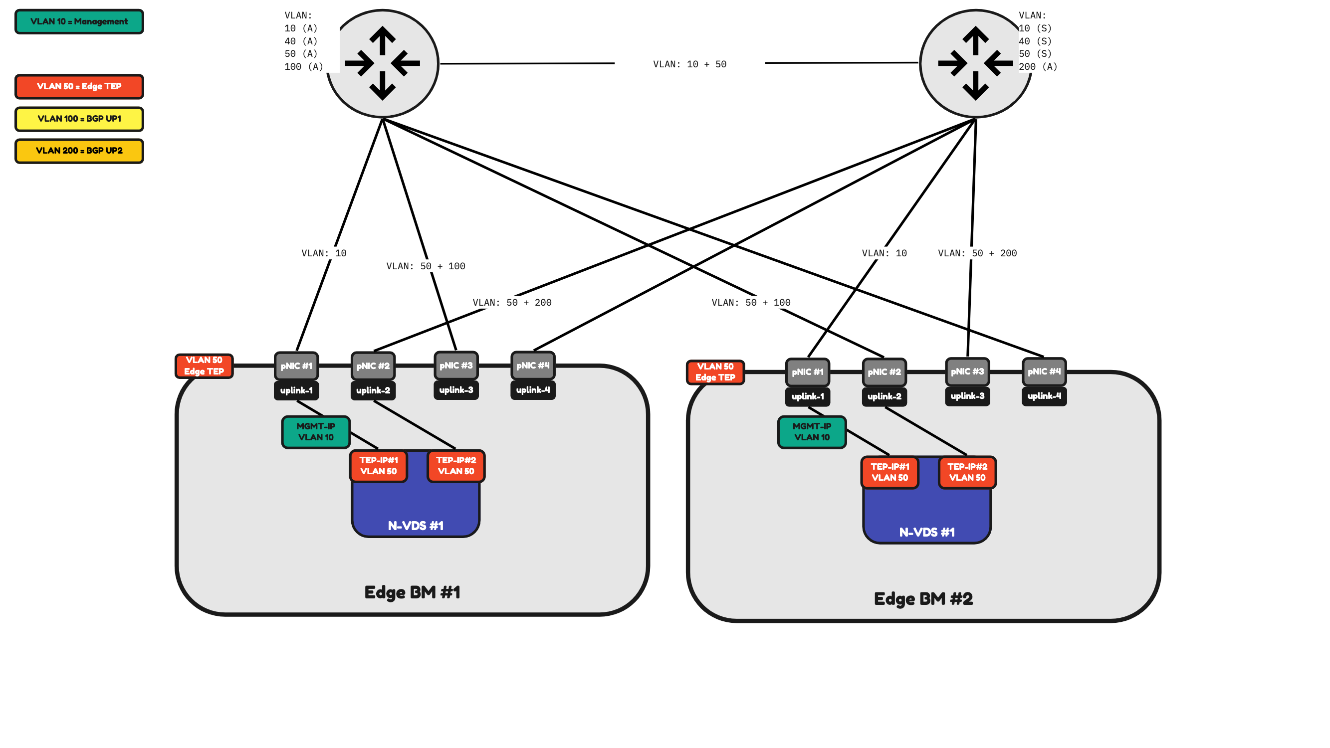
Figure 23:
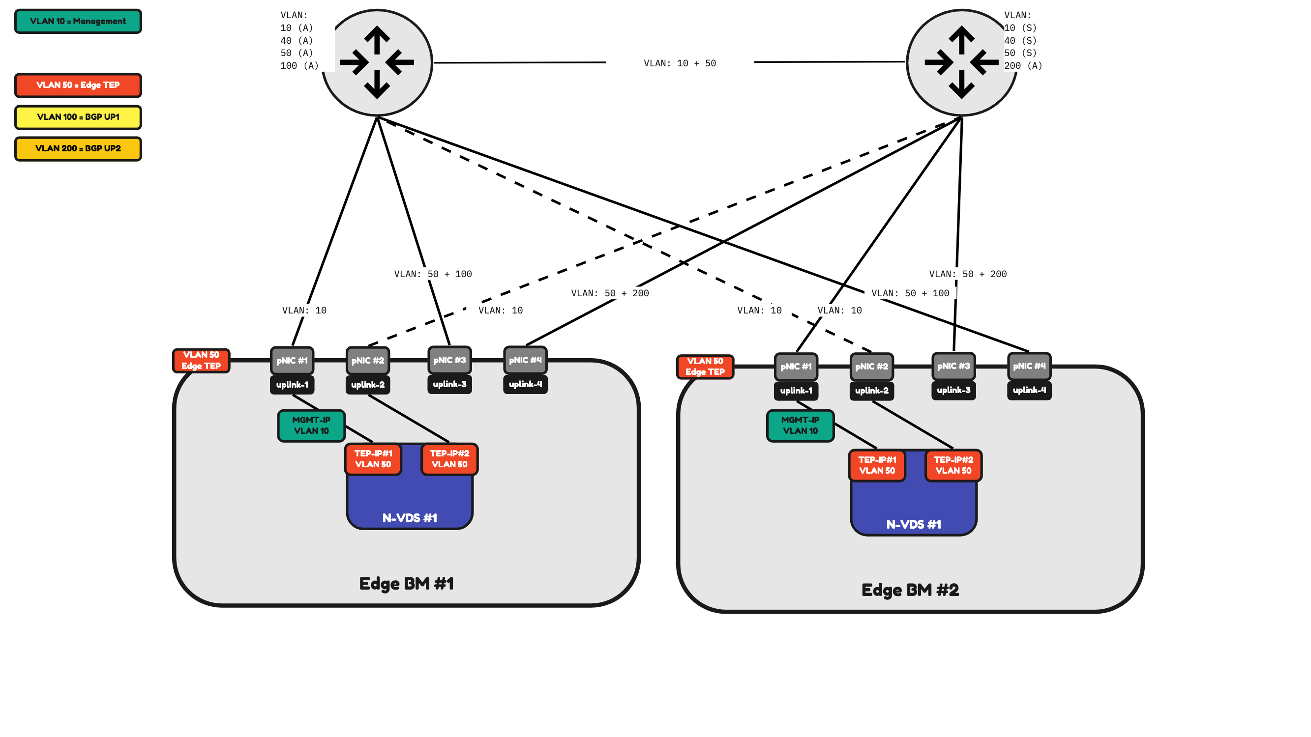
Table 5 will provide you with an overview of how the traffic will be flowing.
ADD TABLE 5
Table 5» 4–pNIC Bare Metal Edge Traffic Mapping 〈Figure 23〉
| Property | Host pNIC |
|---|---|
| Management Traffic | pNIC #1 (active) pNIC #2 (standby) |
| Edge TEP Traffic | pNIC #3 (active) pNIC #4 (active) |
| BGP Uplink 1 Traffic | pNIC #3 for Edge BM#1 pNIC #4 for Edge BM#2 |
| BGP Uplink 2 Traffic | pNIC #4 for Edge BM#1 pNIC #3 for Edge BM#2 |
Table 5: 4-pNIC Bare Metal Edge Traffic Mapping (Figure 23)
Uplink Profiles
Depending on the number of physical interfaces this will determine the way how traffic is (or can be) processed. You can configure (or influence) this using Uplink Profiles.
⚠️ An uplink profile can be applied to (ESXi) Host Transport Nodes and to Edge (Virtual and Bare Metal) Transport Nodes. It is best practice to create dedicated/separate Uplink Profiles for each different type of Uplink Profile you are planning to use.
In Figure 24, Figure 25, and Figure 26 you see that I have created and applied an Uplink Profile to an ESXi host.
To keep things simple, I am working with the following examples with ESXi hosts with two pNICs.
Figure 24 is illustrating an uplink profile that is configured in “Failover Order”. Failover Order means that only one pNIC is used as the active pNIC and the other ones left are all going to be on standby (not used).
The blue VMs (Web, App, and DB) that are hosted on the ESXi host will all send their traffic to Uplink-1 which is attached to pNIC #1. pNIC #2 is unused until pNIC #1 is unavailable for whatever reason.
Figure 24:
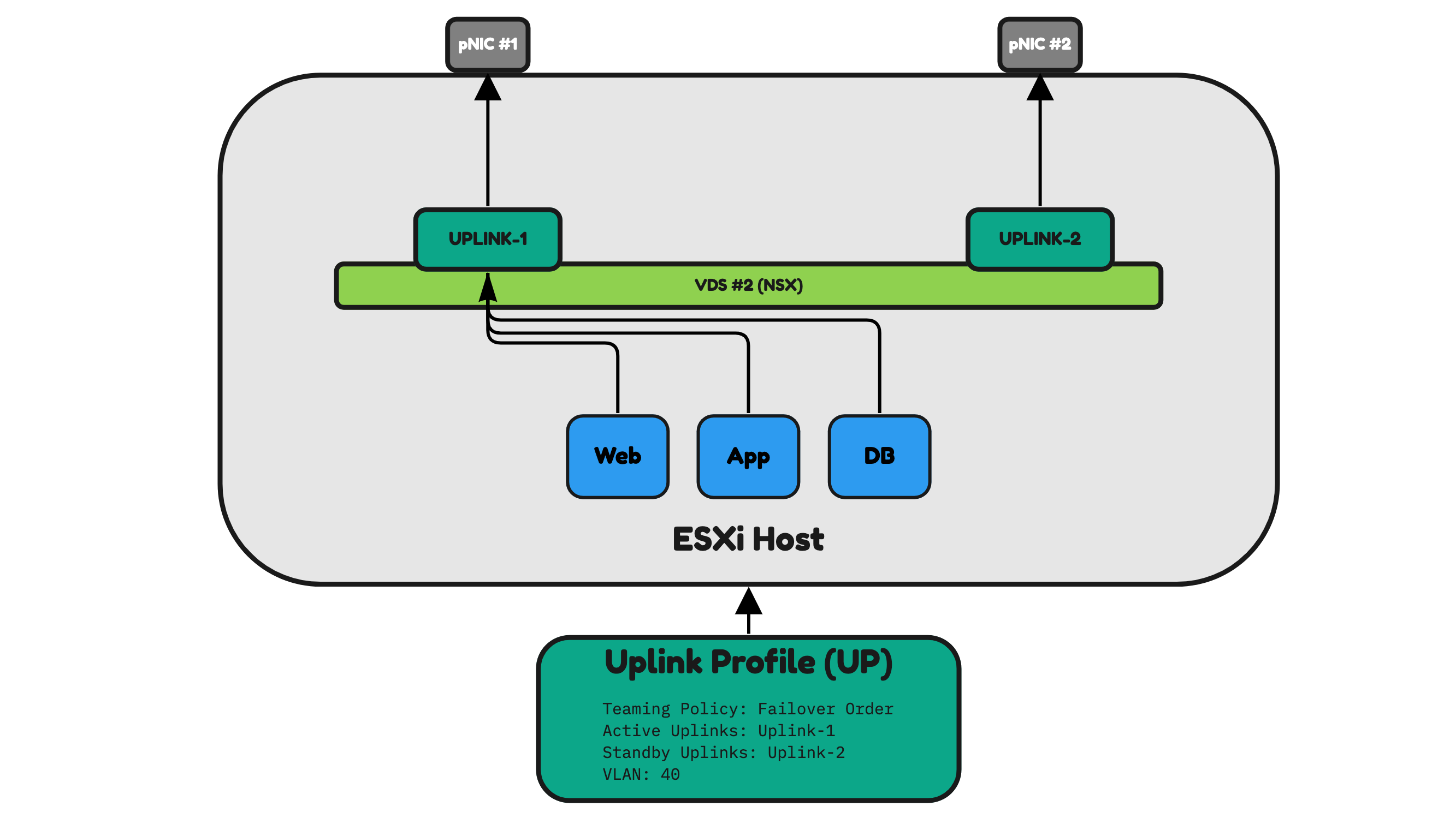
Figure 25 illustrates an uplink profile configured in “Load Balance Source ID”. Load Balance Source ID means that both pNICs are used as the active pNICs.
The blue VMs Web and DB that are hosted on the ESXi host will all send their traffic to Uplink-1 which is attached to pNIC #1. The other blue VM App will all send its traffic to Uplink-2 which is attached to pNIC #2.
When one pNIC is unavailable for whatever reason the other one will be used.
⚠️ The way NSX determines what Uplink/pNIC to select will be done based on the Virtual Port ID of the VDC to which the VM is attached.
Figure 25:
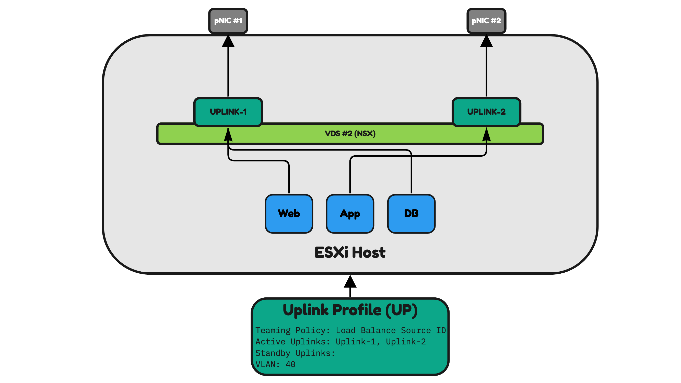
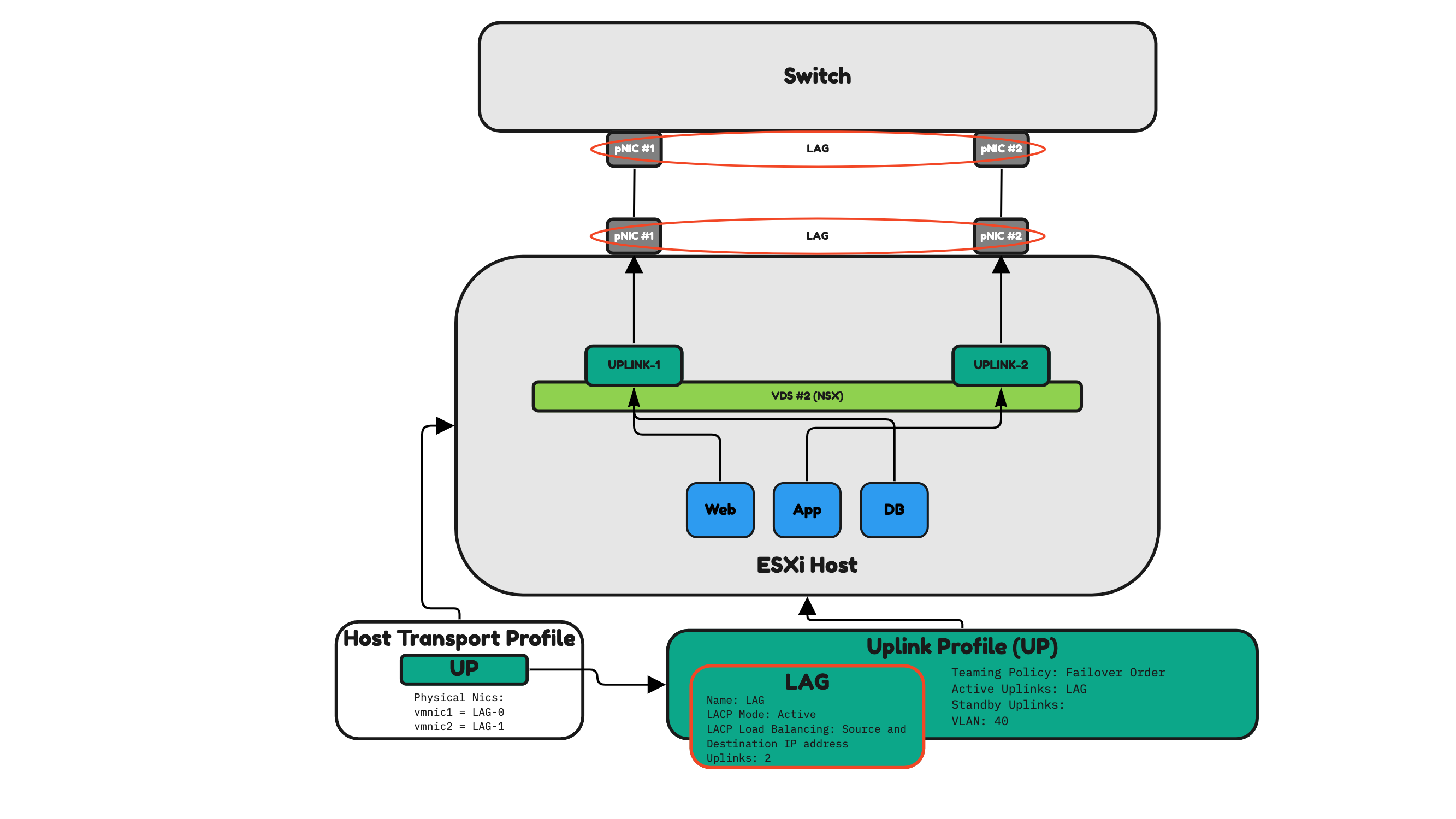
Figure 26 illustrates an uplink profile configured in “LAG”. LAG means that both pNICs are used as the active pNICs just like Load Balance Source ID. The difference here is that with this profile setting it is now possible to use multiple Physical Interfaces and combine these to be logically one. This is also called a Port Channel (or Ether Channel). The traffic distribution between the ESXi host and the Physical Network (Switch) is now done based on the selected LAG algorithm.
Figure 26 is using Source and Destination IP Addresses as the algorithm, and this means that the traffic path that is selected between the physical interfaces (between the ESXi server and the switch) will be based on the source and destination IP addresses.
Figure 26:
NSX Host Transport Profiles and NSX Uplink Profiles and NSX IP Pools
An IP Pool is used to specify the IP addresses that Host Transport Nodes should use for their TEP IP addresses.
The Uplink Profile (like I have just described) determines the way network traffic will flow depending on the number of interfaces.
The Host Transport Profile is used to apply settings to multiple Host Transport Nodes that are part of a vSphere Cluster.
One of the settings that the Host Transport Profile inherits is the settings from the Uplink Profile. The Uplink Profile inherits the settings from the IP Pool.
Figure 27:
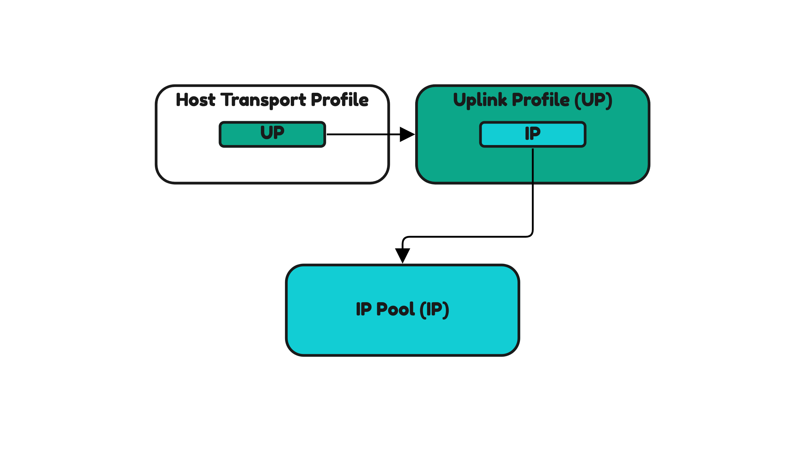
For this reason, when you want to configure your ESXi Hosts for NSX (making them a Host Transport Node) and you are using the Host Transport Profile for this you first need to configure the IP Pool and the Uplink Profile as a dependency (Figure 27).
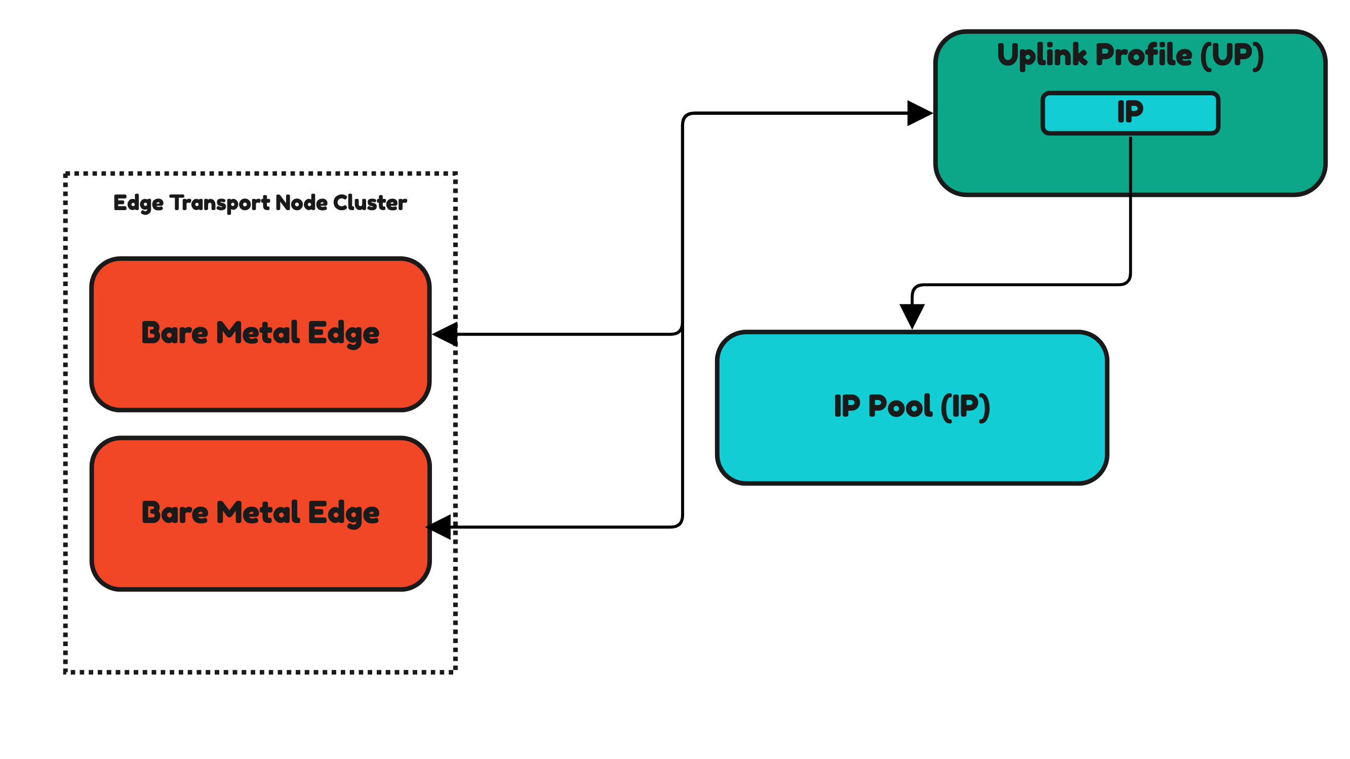
NSX Uplink Profiles and NSX IP Pools and Edge Transport nodes
IP Pools and Uplink Profiles are also used for Edge Transport Nodes.
Edge Transport Nodes (Edge VMs and Bare Metal Edges) do not have profiles as you have seen for hosts. Uplink Profiles are directly applied to the Edges. In Figures 28 and 29 you see this.
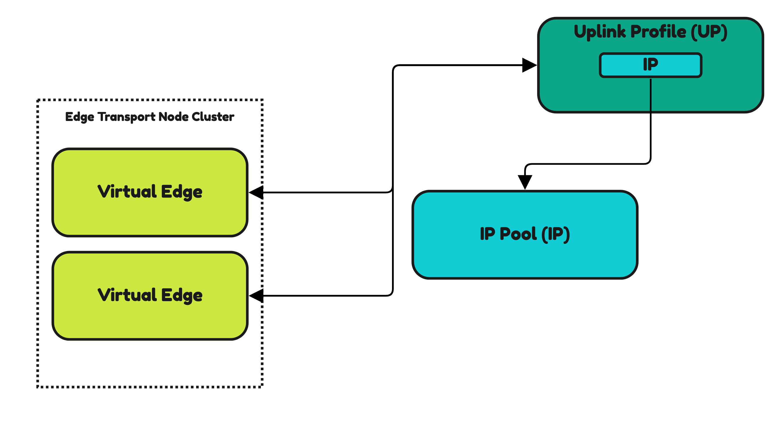
Inside the Uplink Profile, you still need to specify an IP Pool that you need to pre-create up front.
Figure 28:
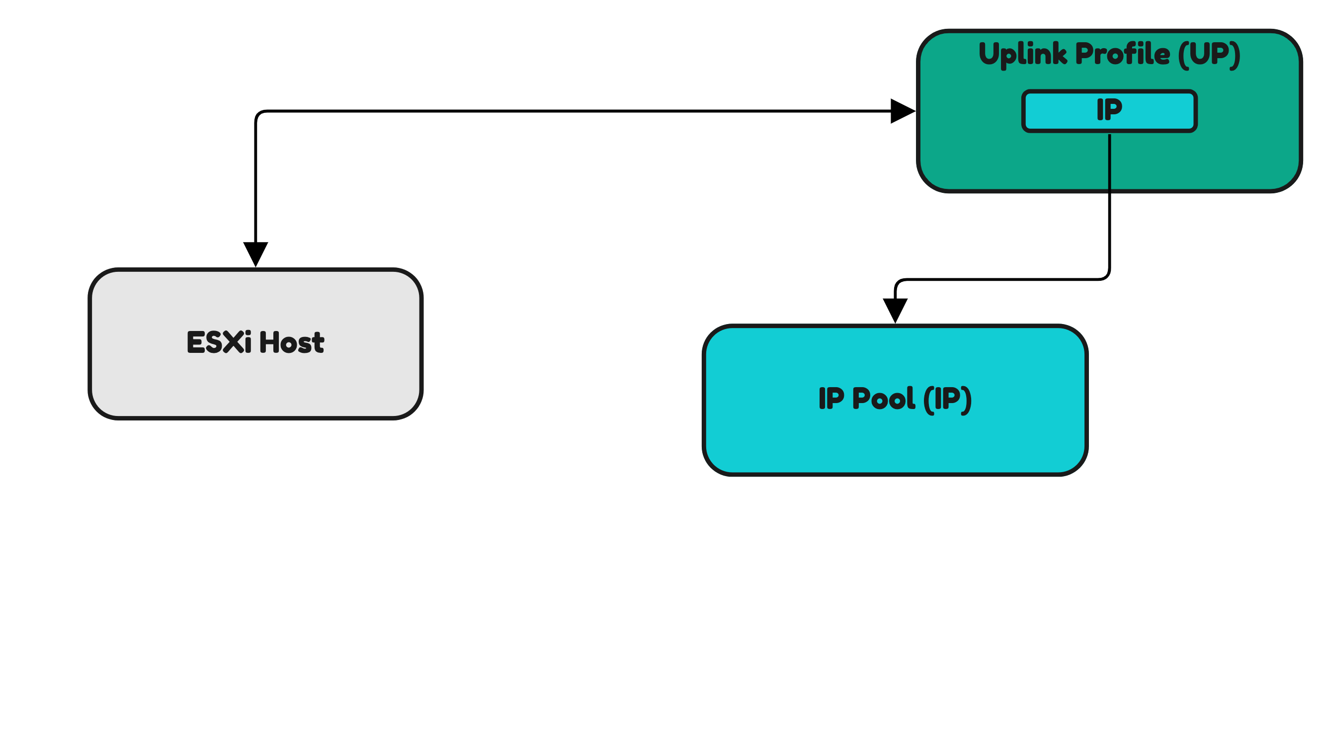
Installing NSX on a standalone Host Transport Node
When you do not want to make use of the Host Transport Profile and only want to configure NSX on standalone hosts you can also apply the Uplink Profiles directly applied to a single host (Figure 30) or to a subset of selected hosts. The principle is the same as this is done for the Edge Transport Nodes
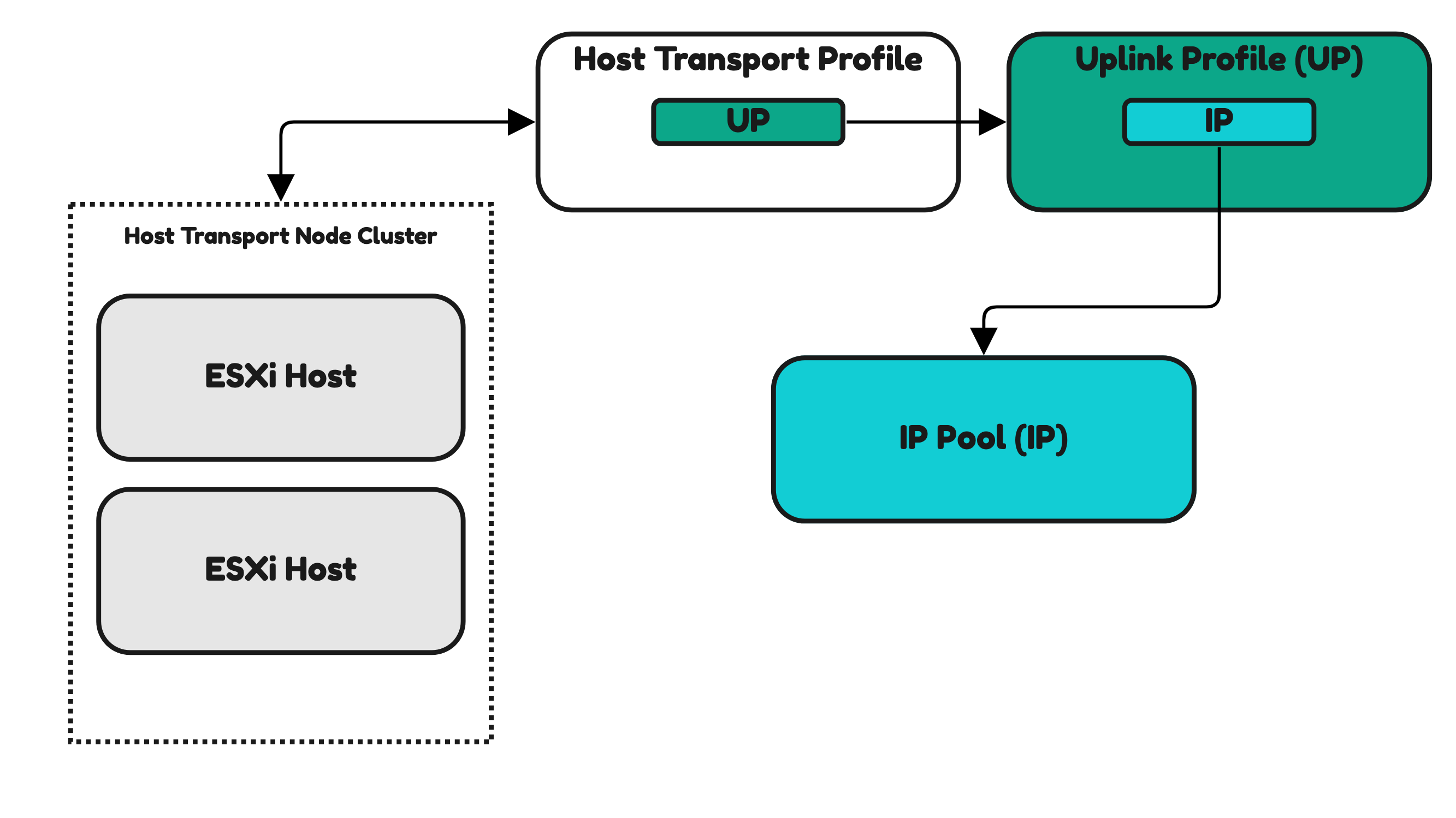
Installing NSX on a 〈vSphere〉 cluster Host Transport Nodes 〈using Host Transport Profiles〉
The Host Transport Profile is used to apply settings to multiple Host Transport Nodes that are part of a vSphere Cluster. In Figure 31 you can see that the Host Transport Profile is used to apply this on a Host Transport Node Cluster (vSphere Cluster).
Figure 29:
Continue with the next section >> NSX License and Compute Managers